
DIY: Short Ram Intake

Thread Starter
Joined: Aug 2003
Posts: 21,620
Likes: 1,252
From: Las Vegas, NV
Rep Power: 512 

DIY: Short Ram Intake
And no, it's not an install guide. Well, kinda. But there's a way to make your own SRI for the 10th gen civic, all you really need is a dremel, a cone filter, a mounting bracket (get creative), and maybe a spare OEM intake cover (the thing you take off to replace the air filter). Overall, cost me like.. 60 bucks, as opposed to the $300-$400 intakes out there.
I got permission from PRL Motorsports to use their pics!
All the pics were taken from their DIY guide for their Cobra CAI over at CivicX.com, and that thread can serve as a DIY guide for any CAI install on the 1.5T platform.
Thread here: PRL Motorsports Cobra CAI Install
Any picture used will have an "Image source: PRL Motorsports" annotation below it.
Since they let me use their pics, I'm gonna give them some free advertising for being awesome.
______________________________________
Alright kids, your neighborhood friendly Riceboy here, and today I'm gonna show you how to make a legitimate SRI on the cheap for the 1.5T. Now, bear a few things in mind:
1) First things first, to give credit where credit is due. The original DIY I followed was posted by user blksprthtchbck� on CivicX.com. Huge thanks to that dude.
2) I can only tell you this for sure works on the non-Si version of the L15B7 engine. I'd imagine it would work on the Si version, but I'd have to take a first-hand look at the intake cover to make sure it's doable.
3) Let's be real. Intakes aren't really power adders. However, the resonator box for the L15B7 is so damn huge that it kills the sound of the turbo spooling (to some extent) and, unlike the PSSSSHHH sound of a BOV (blow off valve), the BPV (bypass valve) recirculates the air back into the intake stream, and the resonator box makes the BPV basically unheard. Any intake will make the turbo spool noise more noticeable, and with this, you can actually hear the BPV open up and recirc the air.
4) Do this at your own risk. It requires hacking up the OEM intake filter cover. If you do this, there's no turning back... that is, unless you buy a spare one. The list price on the cover (part number 17210-5AA-A00) is only $25. It'll prolly run you $40-50 bucks at a dealership, and from hondapartsunlimited, it ran me $33.48 with priority shipping (it would've been about 6 bucks less if I chose the slowest/cheapest shipping method).
5) I took limited pictures and I don't feel like taking it apart (yeah, even though it's easy) to take more. It's upwards of 110F (43C) out, but if you're taking this project on, if you can't figure it out, then you probably shouldn't be taking this project on. I may update this thread at a later date with more pics. At the very least, I will explain a good bit. A large portion of what I'm not going to have pictures for is where I mounted my bracket (it's very intuitive) and how to take out the resonator since that thing sucked to take out from the top. I didn't feel like jacking up my car to install an intake, so that's the reasoning behind the second part.
6) Total time I spent on this DIY was a good 4-4.5 hours. Here's a breakdown of how I spent the time:
How it do
My thoughts and observations on the mod after doing it.
Cost breakdown
-Air cleaner top cover with priority shipping: $30
-AEM Dryflow filter (pn 21-200dk): $60 (I had an AutoZone gift card with like $30 on it)
-Aluminum flat stock: $6-7
-Screws from Ace Hardware (2 M6-1.0x16mm bolts and 2 M4x0.7x10mm hex cap bolts -- used those to replace the pan head screws that secured my MAF sensor): $3
Total (out of pocket) Cost: $70
Most SRIs out there for the 10thgen: $300+
Most CAIs out there for the 10thgen: $400+
_________________________________
DIY SRI V2.0 Edit
Alright, decided to change it up a bit, really because I was bored and one of my friends (he drives a 16 ex-t) showed interest in a DIY SRI. I decided to make me a new one from my original air cleaner cover, but decided a slightly different approach. For the most part, the DIY is the same, but here, I will explain the different approach I took with regards to modding the MAF housing to accept a filter.
This time, I took my time cutting it out. Didn't use a dremel this time because that melted a lot of plastic and I used a razor blade, instead. I also left a lot more of the supporting structure that connected to the mounting bolt (I still retained the single mounting bolt setup).
I also took a trip to Home Depot and purchased a 2" ABS pipe coupler for $1.08+tax. Carefully "welded" it onto the hacked up MAF housing to create a pipe extension for the filter to grab onto.
But Josh... you welded.. plastic...?
Yes, it's a thing. I, however, did not have access to a plastic welder. Instead, I used a soldering iron, melted the plastic pieces together, and it ended up making an air-tight seal around the coupler/MAF interface. A few things I learned/tested/observed, for those that decide to take this venture
So, why 2" coupler? The OD of the coupler was 2.7". I have a new filter on the way that has a flange diameter of 2.75 (AEM P/N 21-202DK). I'm not worried about being able to make up that 50 thou with clamping down on it. Also, the ID of the coupler was larger than that of the MAF housing by about 3mm.
Enough talking about it, here are the pics
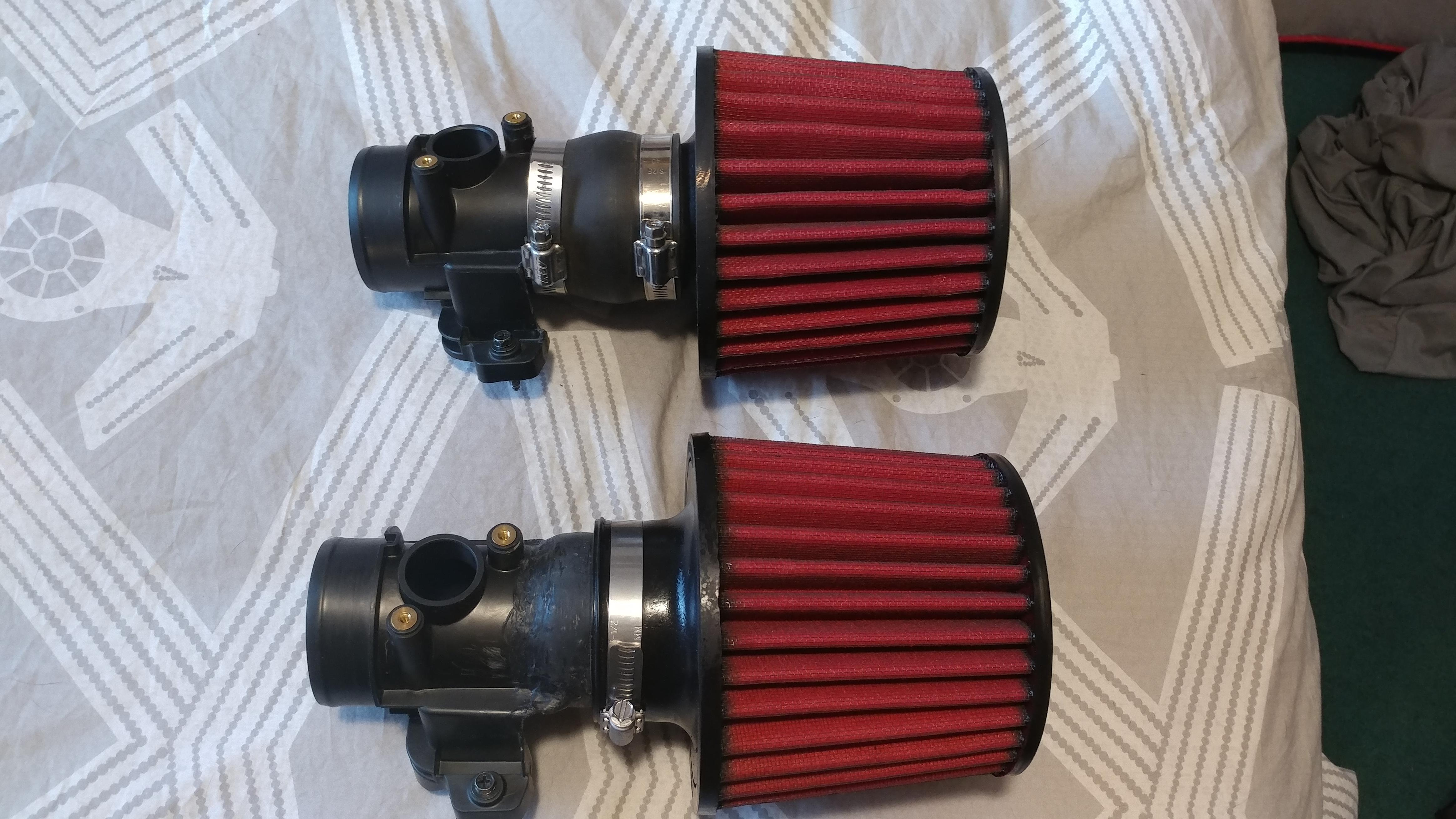
Comparison of V1 (top) and V2 (bottom). V1 is about half an inch overall longer than V2.
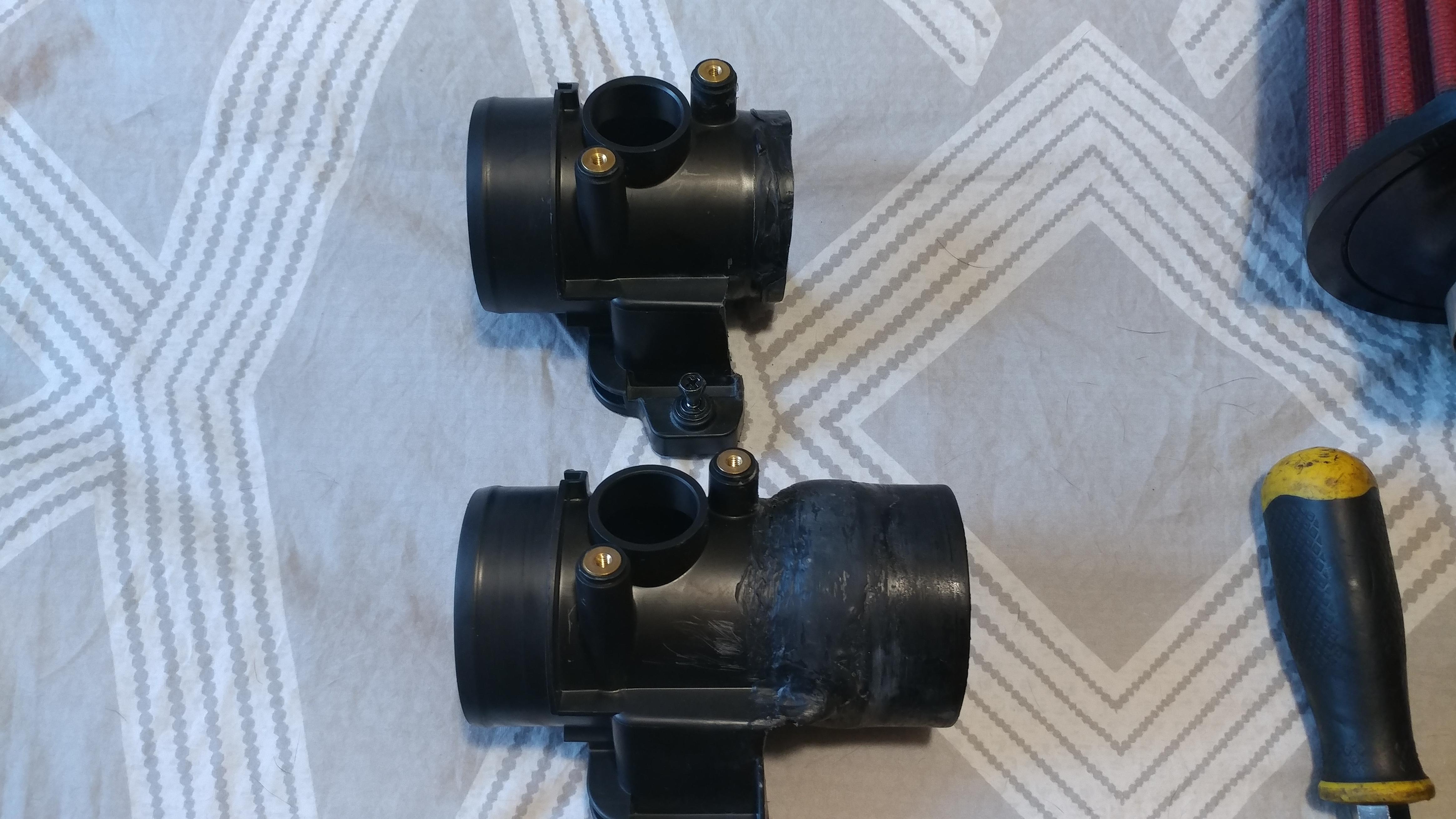
Comparison of V1 (top) and V2 (bottom) sans filters. Note that V1 is immensely shorter than V2, due to the extra added ABS coupler.
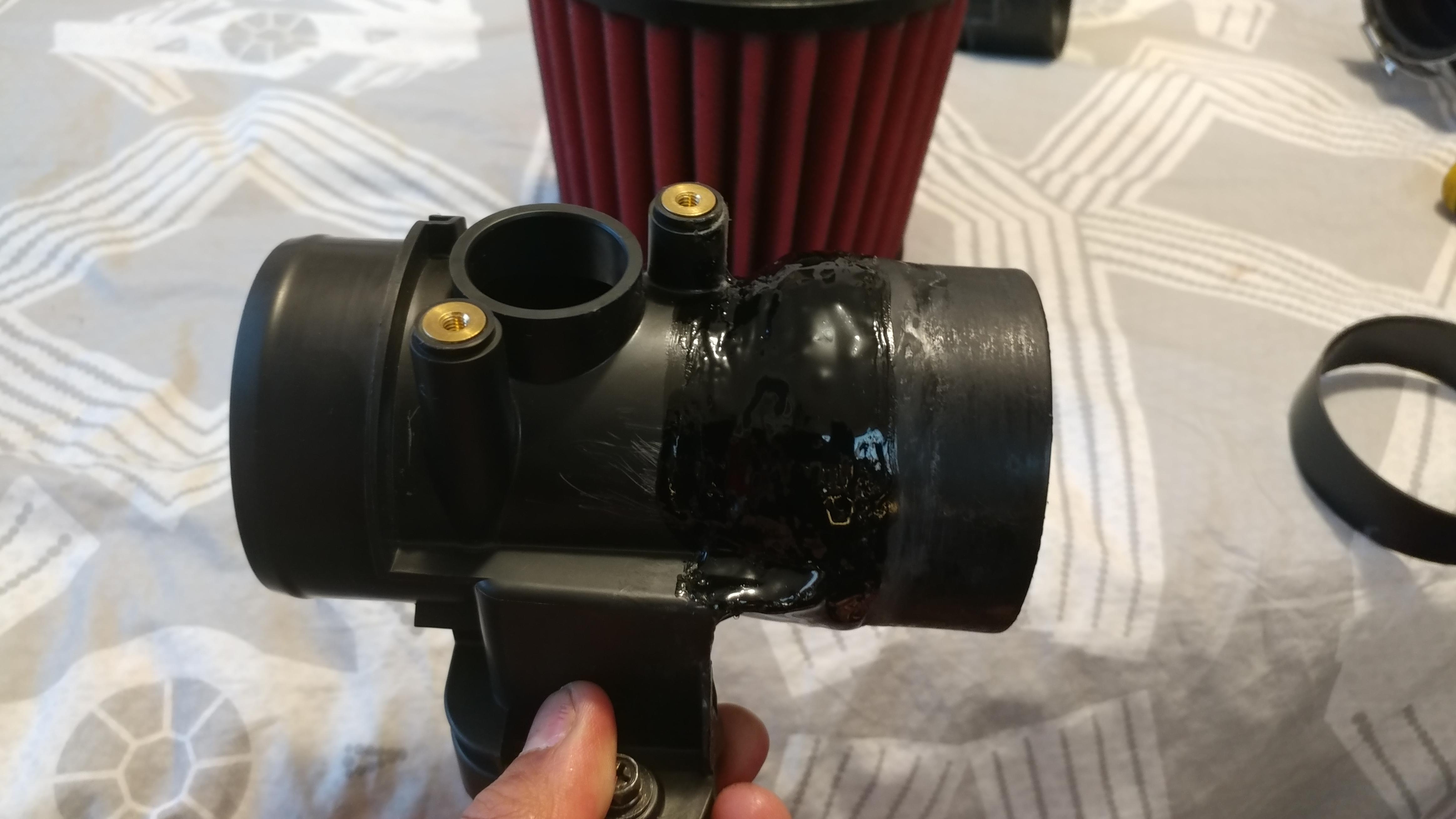
And V2 with the ABS glue painted on. She’s not the prettiest, but even without the ABS glue, she’s held great. I can only assume with the extra plastic, it’ll hold that much better.
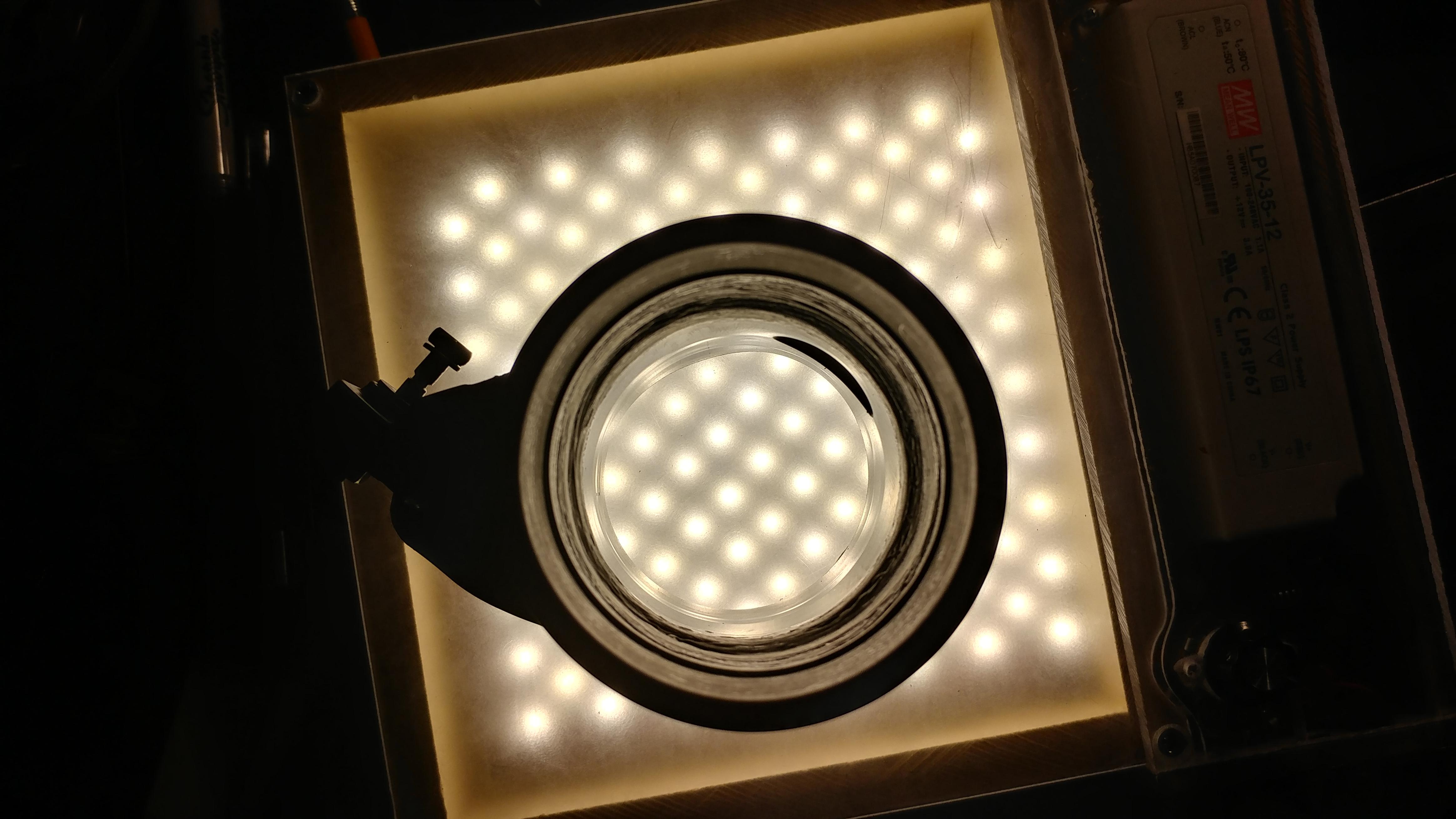
And a look at the inside. You can see the area where the coupler was added onto the MAF housing, and I took some extra Permatex plastic welder and made it a smoother transition to help airflow be smoother. It’s not the smoothest surface, however, but I highly doubt minor imperfections in the surface finish will be of any concern.
I got permission from PRL Motorsports to use their pics!
All the pics were taken from their DIY guide for their Cobra CAI over at CivicX.com, and that thread can serve as a DIY guide for any CAI install on the 1.5T platform.
Thread here: PRL Motorsports Cobra CAI Install
Any picture used will have an "Image source: PRL Motorsports" annotation below it.
Since they let me use their pics, I'm gonna give them some free advertising for being awesome.
"Stage 1" Intake system (drop in filter and silicone hose): $89.99
Non-Si Cobra CAI: $399.99
Si Cobra CAI: $399.99
Non-Si SRI: $299.99
Si SRI: $299.99
SRI to CAI conversion kit: $124.99
CAI to SRI conversion kit: $24.99
For our Canadian friends that want to install a CAI, but can't because the windshield washer reservoir is where the filter would sit..
USDM windshield washer reservoir conversion kit: $74.99
And finally, here's a link to all their 10thgen Civic goodies (including turbo upgrades, FMIC, IC piping, downpipes, etc.)
Alright kids, your neighborhood friendly Riceboy here, and today I'm gonna show you how to make a legitimate SRI on the cheap for the 1.5T. Now, bear a few things in mind:
1) First things first, to give credit where credit is due. The original DIY I followed was posted by user blksprthtchbck� on CivicX.com. Huge thanks to that dude.
2) I can only tell you this for sure works on the non-Si version of the L15B7 engine. I'd imagine it would work on the Si version, but I'd have to take a first-hand look at the intake cover to make sure it's doable.
3) Let's be real. Intakes aren't really power adders. However, the resonator box for the L15B7 is so damn huge that it kills the sound of the turbo spooling (to some extent) and, unlike the PSSSSHHH sound of a BOV (blow off valve), the BPV (bypass valve) recirculates the air back into the intake stream, and the resonator box makes the BPV basically unheard. Any intake will make the turbo spool noise more noticeable, and with this, you can actually hear the BPV open up and recirc the air.
4) Do this at your own risk. It requires hacking up the OEM intake filter cover. If you do this, there's no turning back... that is, unless you buy a spare one. The list price on the cover (part number 17210-5AA-A00) is only $25. It'll prolly run you $40-50 bucks at a dealership, and from hondapartsunlimited, it ran me $33.48 with priority shipping (it would've been about 6 bucks less if I chose the slowest/cheapest shipping method).
5) I took limited pictures and I don't feel like taking it apart (yeah, even though it's easy) to take more. It's upwards of 110F (43C) out, but if you're taking this project on, if you can't figure it out, then you probably shouldn't be taking this project on. I may update this thread at a later date with more pics. At the very least, I will explain a good bit. A large portion of what I'm not going to have pictures for is where I mounted my bracket (it's very intuitive) and how to take out the resonator since that thing sucked to take out from the top. I didn't feel like jacking up my car to install an intake, so that's the reasoning behind the second part.
6) Total time I spent on this DIY was a good 4-4.5 hours. Here's a breakdown of how I spent the time:
-15-20 minutes cutting the MAF housing out and shaping the MAF inlet to receive a cone filter.
-30-45 minutes shaping, cutting, drilling and tapping the aluminum bracket.
-15 minutes painting the bracket (it's hot as ***** out here in Vegas, so the paint dried faster than hell. YMMV).
-3 hours oven-curing the ceramic clearcoat.
-Install maybe took 5-10 minutes, but that time frame is kinda tied in with bracket forming (you'll see why when you read that section of the DIY guide).
So, let's get onto it!-30-45 minutes shaping, cutting, drilling and tapping the aluminum bracket.
-15 minutes painting the bracket (it's hot as ***** out here in Vegas, so the paint dried faster than hell. YMMV).
-3 hours oven-curing the ceramic clearcoat.
-Install maybe took 5-10 minutes, but that time frame is kinda tied in with bracket forming (you'll see why when you read that section of the DIY guide).
Tools required:
- Philips head screwdriver
- 10mm socket (and a 12" extension)
- 5.5mm socket
- 8mm socket
- Pair of pliers
- Dremel (or any other way you can think of to cut ABS plastic and aluminum)
- Power Drill and set of drill bits
- (optional) sanding flapwheel for a dremel
- (optional)M5x.8 tap
Parts Required:
V2 parts edit
- Cone filter. I'd recommend one with a 2.5" flange (AEM dryflow 21-201DK) I used AEM 21-200DK (2.25" flange), and that would require a bit extra to make work. I'll address that later.
- Air cleaner top cover, part number 17210-5AA-A00. Be careful with the part number. Don't do like I did and accidentally order the bottom half (17201-5AA-A00). The part numbers are very, very similar.
- If you go the same route I went (2.25" filter instead of the 2.5"), you'll need a reducing coupler. I'm not gonna lie, no idea what size I used, since I used the intake -> throttle body coupler from my old AEM V2 intake. The install sheet for the 7thgen AEM V2 intake says it's a 2.75" to 2.5" reducer.
- A short length of aluminum flat stock to make your own bracket (I bought a 2"x36"x.125" aluminum flat from Home Depot and cut/bent to size)
- 2-M6x1.0 16mm bolts
- (optional) 1-M5x.8 bolt (the length would be all up to you, since I didn't go this route. This will be addressed later, as well.
V2 parts edit
- 2.75" flange filter (I used AEM P/N 21-202DK) in lieu of 2.25" or 2.5" filter
- 2" ABS pipe coupler from Home Depot (or similar hardware store)
- Plastic welder glue (I'd recommend Permatex black plastic welder)
- optionalSpare ABS pieces and acetone (to make ABS glue/slurry)
- First things first, get the old intake out of there.
- Unplug the MAF sensor and use a pair of pliers to release the bracket from the intake top cover and swing the wiring harness out of the way.

Image source: PRL Motorsports - For this procedure, you only have to take off the right-most hose clamp. If you're installing an intake that replaces the entire flex hose, take off both. Use a 5.5mm socket to loosen the hose clamp and you can slip the flex pipe off the air cleaner cover.

Image source: PRL Motorsports - 4 bolts hold the air cleaner cover onto the casing. Use an 8mm socket or philips head screwdriver to remove those. This is the same procedure you'd use to remove the OEM air filter. That said, once the cover is off, take the filter and put it.. somewhere. You don't need it anymore.

Image source: PRL Motorsports - Next up is the air cleaner case.

Image source: PRL Motorsports
Remove the 2 bolts on the right side (while facing the engine bay) using a 10mm socket and a 12" extension. Now, the case is gonna feel loose like you can pull it out, but something on the front left is holding it down. It's only a rubber grommet piece. Pull upwards with some force and it'll pull right out. PRL states that you can push the box toward the front of the car to separate it from the rubber dampener nipple.

Image source: PRL Motorsports
And here's what the rubber dampener nipple-air cleaner case interface looks like from the front:

Image source: PRL Motorsports - Now the pain in the *** one: the resonator box. It's held on by 2 bolts that use a 10mm socket/wrench, but they thread in from the bottom. The rear-most bolt is easy to get to, as is the bracket that is bolted to the chassis. Remove that bolt and the bolt holding the bracket on, and remove the bracket. The forward-most bolt, however, is a pain.
You have a few options here:- Jack up the car, take the bumper and floor pan out, wiggle your way down there unbolt, and drop it out the bottom. I didn't do it this way because it's a short ram, and I didn't feel like jacking up the car to install a short ram. (Instructions are laid out on PRL's install guide to perform it this way)
- Leave it in there. It will likely rattle around unless you fab up a bracket to keep it still. I didn't do it this way either.
- Wrestle the damn thing out. I did it this way. Ended up breaking a not-very-important tab to release it from the mount. That's only half the battle, though, if you go this route. In order to take the resonator out from the top, I unplugged 2 plugs (just to avoid any potential damage to wiring), and disconnected the intercooler flex piping. From there, channel your inner contortionist and finagle the thing out. It's not easy to do, but it's still very doable.
After all that is said and done, you should have all 3 pieces out. Here's what it looks like assembled, out of the car:
The tab I broke is the bottom-most part pictured (just above the word "body" on my power tower thingy). It still holds the rubber grommet/bolt thingy, just not as securely as it did before. - Unplug the MAF sensor and use a pair of pliers to release the bracket from the intake top cover and swing the wiring harness out of the way.
- Now it's time to meet the piece in question, the air cleaner top cover:
This is the part that needs to be hacked to pieces. Note that the MAF sensor is removed. Keep that sucker in a safe place. This car bases the AFR on that MAF sensor, and that thing has a list price of $200. Don't mess it up. lol
If you look on the inside, there's a flared part where air enters the MAF housing.
- Carefully cut to complete the circle. Take your time with it, don't mess up the MAF housing. Do yourself a favor and leave at least one of the bolt holes (that secures the cover to the casing) attached to the MAF housing. When all is said and done, you end up with something like this:
The flared end is kinda... warped.. on mine because I tried melting it down with boiling water to reshape it down to a 2.25" OD (so I could fit my filter over it). That didn't work too well, but a non-issue the way I have mine set up. You'll also notice I left the bolt hole on the front in tact, since that's what I planned on using to support it all. From all this hacking crap up, this is why I opted to have a spare on hand, in case I f'd up. - Take this time to clean out any plastic shavings. Dunk in water, rub down with a paper towel, repeat as you feel necessary, and allow to dry.
From here, the only pic I have is the installed pic. Use your mind's eye to figure out what I'm talking about. ˢᵒʳʳʸ ᵍᵘʸˢ ᴵ ˢᵘᶜᵏ
- Now it's time to put the filter on the MAF housing you just cut out from the intake cover.
- If you went with the 2.5" flange, I've been told it fits, albeit a hair loose. Should just slap right on and secure it with the included hose clamp.
- If you're like me and went with the 2.25" flange thinking it'd be a more secure fit, there's a bit extra you need to do.
- First, I already had a reducing coupler on hand. If you don't have one, get one. As a reminder, I used the one that came with a 7thgen AEM V2 intake, which the spec sheet said it's 2.75"-2.5".
- Put the big side on the flared side of the MAF housing and secure with a hose clamp.
- Insert the flange of the filter inside the 2.5" side of the coupler, and secure with hose clamp. Trust me, it'll hold just fine. I tried pulling it apart after screwing down the hose clamps, and it didn't go freakin' anywhere.
- Now it's time to fab up a bracket.
- Just forward of the open end of the intake flex pipe, on the upper radiator support, you'll see 2 threaded holes. We're gonna use these bad boys to mount the bracket to. Take a piece of paper, line it up with the top of the support, lay it over the holes, and rub a dirty finger over the bolt holes. Congrats, you just made a hole template to use.
I verified on 2 separate 10thgens (my hatch and my buddy's sedan) that those bolt holes are there. - Find a material to use. I went to Home Depot and spent like.. $6 on a piece of 2x36x.125" flat aluminum stock. However you feel like doing it, make a 90-ish degree bend in the flat stock, leaving yourself plenty of room to play with (give at least 4" one way and 8-10" the other.
- With the short side facing up, eyeball where to cut it down to size. There is a coolant hose you have to make sure you clear with it. Cut it down, adjust as necessary. Once you have your desired length on the short end, affix your template to line up with the top of the bracket-in-progress, and drill those holes out. Make sure they're big enough to accompany an M6-1.0 bolt going through them with a bit of play -- a 1/4" drill bit should do just fine.
- Mount your intake to the intake flex piping (insert MAF outlet into flex piping, line up alignment tab, tighten down hose clamp). After it's installed, swing it out of the way. You'll see why in a sec.
- With the holes drilled, mount that sucker in place using 2 M6-1.0 bolts (I used 16mm length). Swing your newly made intake into the area it's gonna sit and see where that mounting bolt lines up on the flat stock. Want it lower? Open up that 90-degree bend. Want it more centralized on the flat stock? Pull the aluminum stock towards the driver's side more. Customize the shape of the bracket until you have the filter sitting where you want it.
- After you get a good position, use an awl, long *** skinny pencil, the mounting bolt, etc., to mark where to drill your other mounting hole.
- Drill a hole in the marked spot. If you're gonna tap the hole you're about to drill, use a 5/32" drill bit and use an M5-0.8 tap to cut the rest of the way. If not, 3/16" or larger. Note: If you don't tap the hole, you'll need an M5-.8 nut to secure it all. Common sense, yeah, but better to list it and not need it than someone saying, "WHAT SIZE NUT DO I USE?!"
- Mount the bracket in place, mount the intake to the bracket using one of the black bolts that secured the air cleaner cover to the air cleaner case (again, M5-0.8 thread pitch. You can, by all means, buy new hardware if you'd like. A screw is what, at most $1?). Check the fit. If you're happy with it you can stop here or proceed to the following optional steps.
OPTIONAL STEPS - using a sharpie, trace out where the plastic around the mounting bolt on the MAF housing covers the bracket. I wanted to have the entire footprint of the plastic around that bolt touching, so I left the end of the bracket like.. 1" wide. I also gradually tapered the 2" from the bend to the 1" at the end.
- With your dremel (or other metal cutting tool) trim the flat stock to leave what you want, making sure your traced out area is untouched. Use a flapwheel to smoothen the edges. Cut aluminum can be sharp. You can go as far as flapwheeling the mounting holes you made, too.
- Paint with your paint of choice. I did 2 layers of high temp BBQ grill matte black, and 2 layers of VHT satin clear engine coating. Bear in mind the VHT requires baking to fully cure (20min @ 250F, cool for 30 min, 20min @ 400F, cool for 30 min, 20 min @ 600F, cool for 30 min. My oven only goes to 500, so I did 45 minutes at 500F. Worked great, and has worked great for all my firearms parts I've painted with the stuff, too.).
- Just forward of the open end of the intake flex pipe, on the upper radiator support, you'll see 2 threaded holes. We're gonna use these bad boys to mount the bracket to. Take a piece of paper, line it up with the top of the support, lay it over the holes, and rub a dirty finger over the bolt holes. Congrats, you just made a hole template to use.
- After your intake is made and bracket all fabbed up, time to put it all together. Intake should already be installed (as per the bracket fab part), and all you need to do is your final bolt up. Make sure that anything you undid (e.g. 2 electrical plugs and intercooler piping if you went my route to get the intake resonator out) is reinstalled, MAF sensor has been installed in new, hacked up MAF housing intake, MAF sensor plugged in (it'll light up your dash like a Christmas tree if you don't).
- Do a final double check starting from the flex piping up, to ensure everything is on securely: Flex piping hose clamp, MAF sensor screws, MAF sensor plug, hose clamps associated with filter.
- Fire 'er up and enjoy! This is what my DIY intake looks like


My thoughts and observations on the mod after doing it.
- Definitely a difference in sound. I can hear air suction and turbo spool a lot more, which is exactly what I wanted. There's also a slight change in engine tone. Makes it sound like a subtly louder exhaust tone. I've let friends drive my car, so I have been able to notice that my car was creepily quiet while driving away. My buddy drove my car today and it sounded like I had a nice, subtle exhaust system on my car. It made me happy in my pants.
- I thought it was placebo effect until today, but I feel like my car pushed me back in my seat more than normal, thus equating to a bit more power. Same buddy that drove my car (he drives a '16 EX-T), and when we got on the highway, he exclaimed, "holy ****, this thing pulls way harder than my car." Granted, my car is rated at 6 more horsepower than his, and he knows this, but the power difference, he said, felt like far more than 6 horsepower. My other friend that I've let drive my car (she's not a car person) said my car sounds cooler, and she exclaimed, "what the hell? This car has never pushed me back in my seat like that before!" I'm still banking on maybe a few horses freed up in the peak torque band (4250-5500RPM) with some loss down low, but if I need it, I can always "downshift" using my paddle shifters to kick me into the boost range and closer to -- if not in -- the aforementioned RPM band.
- The OEM intake takes up a metric crap ton of real estate. I could probably fit a baby below the DIY intake. Holy crap. I may try and fab up a housing that forces it to take a suction from down low later (google 27won intake and you'll see what I mean), but that would take some doing, and maybe access to someone with a 3D printer.
Cost breakdown
-Air cleaner top cover with priority shipping: $30
-AEM Dryflow filter (pn 21-200dk): $60 (I had an AutoZone gift card with like $30 on it)
-Aluminum flat stock: $6-7
-Screws from Ace Hardware (2 M6-1.0x16mm bolts and 2 M4x0.7x10mm hex cap bolts -- used those to replace the pan head screws that secured my MAF sensor): $3
Total (out of pocket) Cost: $70
Most SRIs out there for the 10thgen: $300+
Most CAIs out there for the 10thgen: $400+
_________________________________
DIY SRI V2.0 Edit
Alright, decided to change it up a bit, really because I was bored and one of my friends (he drives a 16 ex-t) showed interest in a DIY SRI. I decided to make me a new one from my original air cleaner cover, but decided a slightly different approach. For the most part, the DIY is the same, but here, I will explain the different approach I took with regards to modding the MAF housing to accept a filter.
This time, I took my time cutting it out. Didn't use a dremel this time because that melted a lot of plastic and I used a razor blade, instead. I also left a lot more of the supporting structure that connected to the mounting bolt (I still retained the single mounting bolt setup).
I also took a trip to Home Depot and purchased a 2" ABS pipe coupler for $1.08+tax. Carefully "welded" it onto the hacked up MAF housing to create a pipe extension for the filter to grab onto.
But Josh... you welded.. plastic...?
Yes, it's a thing. I, however, did not have access to a plastic welder. Instead, I used a soldering iron, melted the plastic pieces together, and it ended up making an air-tight seal around the coupler/MAF interface. A few things I learned/tested/observed, for those that decide to take this venture
- The intake housing is not made of ABS plastic like I initially thought. That's the reason I bought ABS pipe fittings, so I could use acetone and scrap plastic to make ABS glue. Turns out, it's made of some sort of polyethylene (likely polyethylene terephthalate [PET] or high density polyethylene [HDPE]) or polypropylene (most likely scenario) and does not react with acetone.. At all. Google searching told me that it's nearly impossible to weld poly and ABS, but what I did was melt-mix-smooth, and it seemed to hold just fine. I also stabbed into the ABS coupler a bit to give the molten goo mix something to grab onto. Not enough to pierce, just enough to make a nice sized divot.
- After the welding was done, I took some acetone and painted on the goo-abs interface. A bit of the surface layer of ABS melted enough to grab onto the goo mix. I was worried about strength of the ABS-PE/PP interface since google told me it couldn't be welded. I've dropped this thing, smacked it against my desk, held the MAF housing while punching the ABS side, and it didn’t show any signs of budging. However, test fitting a silicone coupler broke it apart, so I had to try a different route.
- Tested out 3 different plastic glues: JB Weld plastic bonder, Permatex black plastic welder, and Loctite plastic bonder. Also tested out Loctite superglue for ***** and giggles. Nothing really seemed to bond very well to the PE/PP, but all of the above did well with the ABS coupling. The only one that said it bonded to PE/PP was the JB Weld variety, and with my tests, it held up a hair poorer than the Permatex black plastic welder. I mixed [the Permatex stuff] up, ran a bead on both the ABS and PE/PP surfaces and allowed it to cure for an hour. Then I mixed up more black goo and beefed up the thinnest layer (the PE/PP-ABS interface) both inside and out and let it cure for about an hour. Then, for good measure, mixed up some JB Weld plastic bonder and spread a semi-thick layer inside and out, allowed to cure for about an hour, as well. Then one more semi-thick layer of Permatex both inside and out, same hour deal. Then, to make it prettier, took a file to knock down high spots, then some 320grit sandpaper to smoothen, then wet sanded with 800 grit to smoothen some more. Test fit with the same coupler, and it held.
- So, for extra added security, decided to make some ABS glue. We know up to this point the MAF housing is not ABS, but extra plastic in the ABS-PE/PP interface is not a bad idea. Basically, to make ABS glue, I bought a spare ABS coupler from home depot (a 1.5” one, this time, since it was all of 84 cents), shredded it using a razor blade, and put it in a mason jar. In said jar, added enough acetone to cover the pile of ABS with a little bit to spare, and let it sit for 24 hours covered. From there, I literally painted it onto the ABS-PE/PP interface to smoothen out the appearance and add plastic to the area. I mean, as a test piece, I bonded a popsicle stick (used for stirring the glue) to a spare piece of ABS and after a day, it held solidly. Enough to give me peace of mind.
So, why 2" coupler? The OD of the coupler was 2.7". I have a new filter on the way that has a flange diameter of 2.75 (AEM P/N 21-202DK). I'm not worried about being able to make up that 50 thou with clamping down on it. Also, the ID of the coupler was larger than that of the MAF housing by about 3mm.
Enough talking about it, here are the pics
Comparison of V1 (top) and V2 (bottom). V1 is about half an inch overall longer than V2.
Comparison of V1 (top) and V2 (bottom) sans filters. Note that V1 is immensely shorter than V2, due to the extra added ABS coupler.
And V2 with the ABS glue painted on. She’s not the prettiest, but even without the ABS glue, she’s held great. I can only assume with the extra plastic, it’ll hold that much better.
And a look at the inside. You can see the area where the coupler was added onto the MAF housing, and I took some extra Permatex plastic welder and made it a smoother transition to help airflow be smoother. It’s not the smoothest surface, however, but I highly doubt minor imperfections in the surface finish will be of any concern.
Last edited by xRiCeBoYx; Jul 9, 2018 at 11:02 PM.
Thread Starter
Joined: Aug 2003
Posts: 21,620
Likes: 1,252
From: Las Vegas, NV
Rep Power: 512 Re: DIY: Short Ram Intake
Yesterday, helped a buddy install a 27WON intake. The brand is fairly unknown in the aftermarket world, but pretty well known in the 10thgen civic world. Vincent (CEO of 27WON) has been developing parts for the 10thgen by using his own '18 Sport Hatch as a guinea pig. His CAI (technically an SRI/CAI hybrid design) was built from the ground up, 3D designed and milled MAF to emulate stock fuel trims, maintains the cone filter in the engine bay, yet taking a suction from the fenderwell via an.. inverse snorkel, if you will. Kind of a really cool design, and there are secondary suction points in the engine bay in the case of water submergence of the lower tube portion. Kinda pricey at $400, but still a cool design, nonetheless. Also, the aluminum MAF housing that was sent is damn sexy.
Link to the intake
Now, why did I bring this up in this thread? I'm using it as a basis of comparison of my DIY route vs an engineered bought piece. Installation of his intake was pretty straightforward, and 27WON provides some pretty damn good instructions to install. Hardest part of the install was taking the old intake resonator box out. After completing the install, we took a test drive with me in the passenger seat, then we came back and took a drive in my car to compare (I let him drive my car)
His car: 2016 Civic EX-T Sedan CVT
My car: 2018 Civic Sport Hatch CVT w/ paddle shifters
Comparison was done at about 7PM PST with the following conditions:
As stated in #3 on my list of things to bear in mind, this is what I was primarily aiming for when I made my intake. Engine sounds from the 27WON intake were much less restricted than OEM, and you could actually hear turbo spool and BPV recirc. It was still much quieter compared to my DIY intake. Turbo spool and BPV recirc, that is. Sound is what I was after with the intake, so more apparent turbo spool/BPV recirc sound is what I used to determine the winner here.
Winner: DIY Intake
Power Addition
Yes, I stated that intakes aren't much in the way of power adders, however, there will still be some perceived pick-up, particularly in the upper RPM band. 27WON intake definitely gave it a slight bump in the peak torque band (4500+ RPM). My car with the DIY intake still seemed to pull a bit harder. Now, this comparison isn't quite fair, I will mention. The stock L15B7 is rated at 172hp. My Sport Hatch with the "same" L15B7 is rated at 180hp, and considering my little experiment with 87 vs 91 octane, I only run 91 octane in my car. I would have done an actual IAT comparison, but my Torque Pro app and custom PID doesn't read IATs correctly. Even KTuner stepped up to a thread of mine in another forum and couldn't figure it out. Highly likely my buddy would see more of an advantage if it were hot out.
Winner: While technically the DIY intake, it's unfair to compare the same engines with one rated at slightly higher HP, so we'll call it a draw
Aesthetics
Let's be real. Everything we do as modders, there's gotta be a certain level of aesthetics considered while doing things. The 27WON intake came with 4-ply silicone hoses with the brand logo on both hoses, some hefty *** t-bolt hose clamps, and like I mentioned above, that MAF housing was sexy AF. Billet aluminum, milled to spec, and anodized orange (company's specialty color). Furthermore, the filter housing/snorkel assembly. Filter box has a smoked acrylic cover with their logo etched into the top. Four allen screws hold it down for ease of filter removal/cleaning. My ghetto-*** DIY plastic thingy can't hold a candle to it.
Winner: 27WON intake
Cost
27WON intake
$420 after shipping
DIY SRI
Sacrificed air cleaner cover - Free
AEM Filter - $52 shipped from Amazon
ABS coupling from Home Depot - $2 (I bought 2 of 'em, one to make ABS glue, the other you can see in the DIY intake V2 edit in post #1)
Miscellanous hardware (for bracket fab): $5 or so. I did, however, have some metric RivNuts laying around, and all I had to do was buy a couple screws and a length of aluminum flat stock that I Dremeled and bent to the shape I wanted. Then painted and ceramic clear coated with some rattle cans I had laying around (satin black and VHT clear).
Total cost: we'll call it $60 for ease of maths.
Winner: DIY Intake
Final thoughts
Sure, there are pros and cons to both. If performance is what you're after with an intake, you're barking up the wrong tree. Kinda. Many companies out there will claim 10-15hp gains, which we all know is a bunch of BS. 27WON did the right thing and say, "well, yeah, it's like a 3-5hp gain." That, and it's freakin pretty. I will admit, I was eyeing the crap out of the 27WON intake, but would have been quite disappointed at the end result had I bought it. At the end of the day, I'm incredibly happy at the DIY SRI route I went. Only thing I'd change if I could was if I had access to a CNC mill and a block of metal to carve it from, or access to a 3D printer capable of printing with materials that can withstand higher temps than most 3D printed items. That said.. If someone has access to those things, I 3D modeled it just in case measurements are kinda rough, however. I don't have access to precision measuring devices, only a digital inside/outside/depth caliper combo.
Link to the intake
Now, why did I bring this up in this thread? I'm using it as a basis of comparison of my DIY route vs an engineered bought piece. Installation of his intake was pretty straightforward, and 27WON provides some pretty damn good instructions to install. Hardest part of the install was taking the old intake resonator box out. After completing the install, we took a test drive with me in the passenger seat, then we came back and took a drive in my car to compare (I let him drive my car)
His car: 2016 Civic EX-T Sedan CVT
My car: 2018 Civic Sport Hatch CVT w/ paddle shifters
Comparison was done at about 7PM PST with the following conditions:
ambient temperature: ~70F
humidity: 20%
atm pressure: 30.13" Hg
altitude: ~2500ft
Soundhumidity: 20%
atm pressure: 30.13" Hg
altitude: ~2500ft
As stated in #3 on my list of things to bear in mind, this is what I was primarily aiming for when I made my intake. Engine sounds from the 27WON intake were much less restricted than OEM, and you could actually hear turbo spool and BPV recirc. It was still much quieter compared to my DIY intake. Turbo spool and BPV recirc, that is. Sound is what I was after with the intake, so more apparent turbo spool/BPV recirc sound is what I used to determine the winner here.
Winner: DIY Intake
Power Addition
Yes, I stated that intakes aren't much in the way of power adders, however, there will still be some perceived pick-up, particularly in the upper RPM band. 27WON intake definitely gave it a slight bump in the peak torque band (4500+ RPM). My car with the DIY intake still seemed to pull a bit harder. Now, this comparison isn't quite fair, I will mention. The stock L15B7 is rated at 172hp. My Sport Hatch with the "same" L15B7 is rated at 180hp, and considering my little experiment with 87 vs 91 octane, I only run 91 octane in my car. I would have done an actual IAT comparison, but my Torque Pro app and custom PID doesn't read IATs correctly. Even KTuner stepped up to a thread of mine in another forum and couldn't figure it out. Highly likely my buddy would see more of an advantage if it were hot out.
Winner: While technically the DIY intake, it's unfair to compare the same engines with one rated at slightly higher HP, so we'll call it a draw
Aesthetics
Let's be real. Everything we do as modders, there's gotta be a certain level of aesthetics considered while doing things. The 27WON intake came with 4-ply silicone hoses with the brand logo on both hoses, some hefty *** t-bolt hose clamps, and like I mentioned above, that MAF housing was sexy AF. Billet aluminum, milled to spec, and anodized orange (company's specialty color). Furthermore, the filter housing/snorkel assembly. Filter box has a smoked acrylic cover with their logo etched into the top. Four allen screws hold it down for ease of filter removal/cleaning. My ghetto-*** DIY plastic thingy can't hold a candle to it.
Winner: 27WON intake
Cost
27WON intake
$420 after shipping
DIY SRI
Sacrificed air cleaner cover - Free
AEM Filter - $52 shipped from Amazon
ABS coupling from Home Depot - $2 (I bought 2 of 'em, one to make ABS glue, the other you can see in the DIY intake V2 edit in post #1)
Miscellanous hardware (for bracket fab): $5 or so. I did, however, have some metric RivNuts laying around, and all I had to do was buy a couple screws and a length of aluminum flat stock that I Dremeled and bent to the shape I wanted. Then painted and ceramic clear coated with some rattle cans I had laying around (satin black and VHT clear).
Total cost: we'll call it $60 for ease of maths.
Winner: DIY Intake
Final thoughts
Sure, there are pros and cons to both. If performance is what you're after with an intake, you're barking up the wrong tree. Kinda. Many companies out there will claim 10-15hp gains, which we all know is a bunch of BS. 27WON did the right thing and say, "well, yeah, it's like a 3-5hp gain." That, and it's freakin pretty. I will admit, I was eyeing the crap out of the 27WON intake, but would have been quite disappointed at the end result had I bought it. At the end of the day, I'm incredibly happy at the DIY SRI route I went. Only thing I'd change if I could was if I had access to a CNC mill and a block of metal to carve it from, or access to a 3D printer capable of printing with materials that can withstand higher temps than most 3D printed items. That said.. If someone has access to those things, I 3D modeled it just in case measurements are kinda rough, however. I don't have access to precision measuring devices, only a digital inside/outside/depth caliper combo.
Last edited by xRiCeBoYx; Oct 19, 2018 at 12:47 AM.

Thread
Thread Starter
Honda Civic Forum
Replies
Last Post
xRiCeBoYx
Engine Performance Modifications
29
Oct 23, 2021 08:11 AM
gearbox
7th Gen Do It Yourself Articles
19
Jul 10, 2013 06:08 PM

