
2004 Civic EX: Need help with upstream O2 sensor wiring and testing


Thread Starter
Registered!!
Joined: Feb 2012
Posts: 18
Likes: 0
From: Westchester, NY
Rep Power: 0 
Hi I have a 2004 Civic EX and it has been throwing two codes related to the upstream O2 sensor (the one before the catalytic converter). The codes are P0135 and P0134.
About two months ago I asked in the general 7th gen forum for some testing advice but I was advised to replace the sensor. That thread can be found here:
Request: Good how-to on testing oxygen/airflow sensor - Honda Civic Forum
Before I replace the sensor though I would like to check the circuitry to make sure it's working properly. I'm making a request here and maybe someone has some information.
I found a thread with some detailed testing information, but I think some of it is for 2004 LX not EX:
civic: o2 sensor i bought from dealership i trace..ecu..comes back - JustAnswer
I have tested fuses #2 and #4 which are related to the AF sensor. I also took out the fuses and used my voltmeter in the ports with the negative probe on top and the positive probe on the bottom to measure the voltage. The port where #2 is shows maybe 7 volts when the car is running. The port where #4 is shows maybe 14 volts when the car is running. Are those values normal?
Here is the the diagram for the fusebox under the steering wheel:
http://dl.dropboxusercontent.com/u/60718947/Civic/Fusebox%20under%20steering%20wheel.gif
Here is what I think might be the PGM-FI / O2 wiring diagram for the 2004 Civic EX, same as found on the justanswer page. But it may be the 2004 Civic LX and so I need some confirmation on whether I'm looking at the right diagram for my car:
http://dl.dropboxusercontent.com/u/60718947/Civic/O2%20Sensor%20-%20Upstream/PGM-FI%20System.gif
I removed the AF sensor relay from behind the glovebox and have tested it and it seems to be working. It is an OMRON G8HN-UA-007607.

That arrow points to the AF relay's port. There are 5 female parts on the port. The one in the middle in the back is not used. Power goes through the back left and back right when the car is in II (Engine on or off). That causes the relay to connect the closest two. Here is a picture:

When I tested the back two I inserted the negative probe in the back left and the positive probe in the back right. My voltmeter at 12v DC showed:
Nothing when the key is in position 0
12v when the key is in position II - Engine off
14.5v when the key is in position II - Engine running
When I tested the front two I inserted the negative probe in the closest and the positive probe in the second closest. My voltmeter at 12v DC showed:
11.5 when the key is in position 0
7v when the key is in position II - Engine off
When I start the car it briefly spikes to 15v and then:
9v when the key is in position II - Engine running
Here is a YouTube video I made that shows the testing of the front two:
[youtube]fy6-H5bxzgs[/youtube]But I don't know if that's normal. Why is the heater being sent 9 volts? Shouldn't it be sent 12? Does anyone have the spec on that?
I also checked the harness to the oxygen sensor for melting wire etc. I connected my positive probe to PIN4 on the male side and connected my negative probe to battery negative. It read 12v. That's correct isn't it?
Any advice or wiring diagrams specific to 2004 Civic EX would be appreciated. Also I need to know how to test the sensor. It seems wideband sensors may have a different testing procedure from narrowband? How are those ohms/resistance rules? I borrowed a working generic chinese wideband from someone and checked ohms on pins 3 & 4 and it shows 0 ohms (the needle moves all the way to the right) on his but on the one in my civic the needle doesn't move and stays at the left (infinity symbol). Am I comparing apples and oranges here?
Also I have hooked up torque and attempted to monitor the sensor but as I expected because of the no signal code there was no signal.
Thanks
About two months ago I asked in the general 7th gen forum for some testing advice but I was advised to replace the sensor. That thread can be found here:
Request: Good how-to on testing oxygen/airflow sensor - Honda Civic Forum
Before I replace the sensor though I would like to check the circuitry to make sure it's working properly. I'm making a request here and maybe someone has some information.
I found a thread with some detailed testing information, but I think some of it is for 2004 LX not EX:
civic: o2 sensor i bought from dealership i trace..ecu..comes back - JustAnswer
I have tested fuses #2 and #4 which are related to the AF sensor. I also took out the fuses and used my voltmeter in the ports with the negative probe on top and the positive probe on the bottom to measure the voltage. The port where #2 is shows maybe 7 volts when the car is running. The port where #4 is shows maybe 14 volts when the car is running. Are those values normal?
Here is the the diagram for the fusebox under the steering wheel:
http://dl.dropboxusercontent.com/u/60718947/Civic/Fusebox%20under%20steering%20wheel.gif
Here is what I think might be the PGM-FI / O2 wiring diagram for the 2004 Civic EX, same as found on the justanswer page. But it may be the 2004 Civic LX and so I need some confirmation on whether I'm looking at the right diagram for my car:
http://dl.dropboxusercontent.com/u/60718947/Civic/O2%20Sensor%20-%20Upstream/PGM-FI%20System.gif
I removed the AF sensor relay from behind the glovebox and have tested it and it seems to be working. It is an OMRON G8HN-UA-007607.
That arrow points to the AF relay's port. There are 5 female parts on the port. The one in the middle in the back is not used. Power goes through the back left and back right when the car is in II (Engine on or off). That causes the relay to connect the closest two. Here is a picture:
When I tested the back two I inserted the negative probe in the back left and the positive probe in the back right. My voltmeter at 12v DC showed:
Nothing when the key is in position 0
12v when the key is in position II - Engine off
14.5v when the key is in position II - Engine running
When I tested the front two I inserted the negative probe in the closest and the positive probe in the second closest. My voltmeter at 12v DC showed:
11.5 when the key is in position 0
7v when the key is in position II - Engine off
When I start the car it briefly spikes to 15v and then:
9v when the key is in position II - Engine running
Here is a YouTube video I made that shows the testing of the front two:
[youtube]fy6-H5bxzgs[/youtube]But I don't know if that's normal. Why is the heater being sent 9 volts? Shouldn't it be sent 12? Does anyone have the spec on that?
I also checked the harness to the oxygen sensor for melting wire etc. I connected my positive probe to PIN4 on the male side and connected my negative probe to battery negative. It read 12v. That's correct isn't it?
Any advice or wiring diagrams specific to 2004 Civic EX would be appreciated. Also I need to know how to test the sensor. It seems wideband sensors may have a different testing procedure from narrowband? How are those ohms/resistance rules? I borrowed a working generic chinese wideband from someone and checked ohms on pins 3 & 4 and it shows 0 ohms (the needle moves all the way to the right) on his but on the one in my civic the needle doesn't move and stays at the left (infinity symbol). Am I comparing apples and oranges here?
Also I have hooked up torque and attempted to monitor the sensor but as I expected because of the no signal code there was no signal.
Thanks
If you think a good mechanic is expensive, try hiring a bad one
Joined: Dec 2011
Posts: 32,017
Likes: 256
From: Midwest. Aiming about mid-chest
Rep Power: 519 

Re: 2004 Civic EX: Need help with upstream O2 sensor wiring and testing
This one appears to match the EX diagram I have, at least as far as the A/F sensor section is concerned.
EDIT: Actually, nether diagram matched perfectly, refer to what I wrote below.
Ohm test the heater circuit of the sensor itself. The heater portion of the sensor (and it's related circuits) is the only thing the P0135 code is concerned with.
Code P0134 can be caused by P0135.
Solve the P0135 problem, ignore P0134 (for now).
The info in the yahoo link appears to also cover an EX model. What parts are you concerned with?
Quick glance at my info shows EX and LX are pretty close to the same with exception of wiring diagrams---placement on the car (you can't see those links) and terminal numbering inside the sensor connector, but wire colors and functions appear consistent regardless of the car. (The tech on the yahoo answer posted up diagrams from both LX and ?)
Let me know if you find discrepancies between the car and the info, and I will try to get a closer look at the info.
You aren't really gaining anything that way.
The computer is controlling the ground (at PCM terminal A1) and you are picking that up through the wiring and sensor, from afar.
The computer does not necessarily turn on the ground (activate the heater) as soon as the engine is running.
The computer can vary the ground to manipulate the heating of the sensor too. It doesn't necessarily have to be completely grounded at all times of operation.
The computer can shut off the heater circuits if it detects a problem, such as incorrect resistance.
EDIT: Actually, nether diagram matched perfectly, refer to what I wrote below.
Also I need to know how to test the sensor
Code P0134 can be caused by P0135.
Solve the P0135 problem, ignore P0134 (for now).
The info in the yahoo link appears to also cover an EX model. What parts are you concerned with?
Quick glance at my info shows EX and LX are pretty close to the same with exception of wiring diagrams---placement on the car (you can't see those links) and terminal numbering inside the sensor connector, but wire colors and functions appear consistent regardless of the car. (The tech on the yahoo answer posted up diagrams from both LX and ?)
Let me know if you find discrepancies between the car and the info, and I will try to get a closer look at the info.
When I tested the front two I inserted the negative probe in the closest and the positive probe in the second closest. My voltmeter at 12v DC showed:
11.5 when the key is in position 0
7v when the key is in position II - Engine off
When I start the car it briefly spikes to 15v and then:
9v when the key is in position II - Engine running
11.5 when the key is in position 0
7v when the key is in position II - Engine off
When I start the car it briefly spikes to 15v and then:
9v when the key is in position II - Engine running
The computer is controlling the ground (at PCM terminal A1) and you are picking that up through the wiring and sensor, from afar.
The computer does not necessarily turn on the ground (activate the heater) as soon as the engine is running.
The computer can vary the ground to manipulate the heating of the sensor too. It doesn't necessarily have to be completely grounded at all times of operation.
The computer can shut off the heater circuits if it detects a problem, such as incorrect resistance.
Last edited by ezone; Nov 9, 2013 at 10:42 AM. Reason: because I can!
Thread Starter
Registered!!
Joined: Feb 2012
Posts: 18
Likes: 0
From: Westchester, NY
Rep Power: 0 Re: 2004 Civic EX: Need help with upstream O2 sensor wiring and testing
Anything you think I should test. I'll do the ohms test but I wonder if there is something more complete for testing both the male and female sides of the sensor harness. Thanks
If you think a good mechanic is expensive, try hiring a bad one
Joined: Dec 2011
Posts: 32,017
Likes: 256
From: Midwest. Aiming about mid-chest
Rep Power: 519 Re: 2004 Civic EX: Need help with upstream O2 sensor wiring and testing
Outlined in the Yahoo link.
Refer to wire diagrams, go by wire colors. I rely heavily on color as my guide. Almost never use terminal positions unless I absolutely must.
The two black wires of the sensor are where you perform the ohm check.
Not this time.
Whatcha got? Check the spec given in the Yahoo link.
I have a spec of 3.0-3.6 ohms here, the info in the link is lower.
Let's see what yours has and go from there.
Cold, sensor at room temperature.
If the ohm test doesn't pass, then that's a fail. Replace.
If it does pass, then continue testing elsewhere. Follow the Yahoo link info, that looked pretty comprehensive.
Got an actual service manual of your own?
I believe pins 3 and 4 of the harness go to the heater. There is female 3 and 4 coming from the sensor side of the harness and that is where I will insert my probes.
The two black wires of the sensor are where you perform the ohm check.
Does it matter which probe (pos/neg) I use for which pin,
and also what is the resistance to look for?
I have a spec of 3.0-3.6 ohms here, the info in the link is lower.
Let's see what yours has and go from there.
Do I do it while the car is cool/off or hot/running?
Anything you think I should test. I'll do the ohms test but I wonder if there is something more complete for testing both the male and female sides of the sensor harness. Thanks
If it does pass, then continue testing elsewhere. Follow the Yahoo link info, that looked pretty comprehensive.
Got an actual service manual of your own?
Thread Starter
Registered!!
Joined: Feb 2012
Posts: 18
Likes: 0
From: Westchester, NY
Rep Power: 0 Re: 2004 Civic EX: Need help with upstream O2 sensor wiring and testing
Thanks for your help ezone. I do not have a service manual of my own. Are you aware of anything available online that is a good resource for the 2004 Civic EX?
There was no ohms response on the heater circuit of the old sensor so I ended up buying an AC Delco 213-2850 replacement O2 sensor. I posted on that in the other thread here.
I used Torque to monitor the Emissions Readiness s/DTC to determine when all the emissions tests had passed so I could take the car in for inspection. The car passed. One odd thing though, and I don't know if this is normal or not but Torque doesn't show voltage from the O2 sensor in bank 1 sensor 1 (the one replaced).
Here's a screenshot:
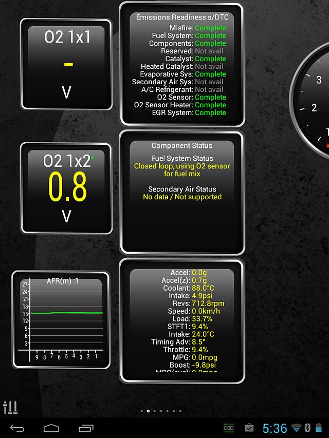
Also now AFR shows 15 consistently. When the O2 wasn't working it showed 12 consistently.
There was no ohms response on the heater circuit of the old sensor so I ended up buying an AC Delco 213-2850 replacement O2 sensor. I posted on that in the other thread here.
I used Torque to monitor the Emissions Readiness s/DTC to determine when all the emissions tests had passed so I could take the car in for inspection. The car passed. One odd thing though, and I don't know if this is normal or not but Torque doesn't show voltage from the O2 sensor in bank 1 sensor 1 (the one replaced).
Here's a screenshot:
Also now AFR shows 15 consistently. When the O2 wasn't working it showed 12 consistently.
If you think a good mechanic is expensive, try hiring a bad one
Joined: Dec 2011
Posts: 32,017
Likes: 256
From: Midwest. Aiming about mid-chest
Rep Power: 519 Re: 2004 Civic EX: Need help with upstream O2 sensor wiring and testing
There is a thread here with links to online manuals, but I cannot vouch for the authenticity or applicability to your particular car.
If the manual is for a different country than where you are, it's up to you to figure that out.
https://www.civicforums.com/forums/1...e-updated.html

Thread
Thread Starter
Honda Civic Forum
Replies
Last Post
Sarahwv2910
Mechanical Problems/Vehicle Issues and Fix-it Forum
22
Jun 17, 2015 12:35 PM
thana
Mechanical Problems/Vehicle Issues and Fix-it Forum
1
Jun 15, 2015 11:58 PM
McLean
Mechanical Problems/Vehicle Issues and Fix-it Forum
2
Jun 13, 2015 10:32 AM
01civicboi
Parts and Products
1
Feb 27, 2002 01:39 PM

