
Pull ECU Codes?

Thread Starter
LOCO!! And The Papers To Prove It
Joined: Apr 2012
Posts: 76
Likes: 0
Rep Power: 0 
Pull ECU Codes?
1990 Civic Dx.
I know where the ECU is. And vaguely remember I need to short something out to get it to show the codes, but I can't remember what I need to short out. I can't find it on the web anywhere, Can anyone tell me what I need to short out to get the ECU to dispaly the codes? Thanks kevin
I know where the ECU is. And vaguely remember I need to short something out to get it to show the codes, but I can't remember what I need to short out. I can't find it on the web anywhere, Can anyone tell me what I need to short out to get the ECU to dispaly the codes? Thanks kevin

Registered!!
Joined: Sep 2012
Posts: 8
Likes: 0
Rep Power: 0 Re: Pull ECU Codes?
I found this on the web dont know if this will help
See that green rubber cover that contains TWO plugs right above your ECU? Remove the one with TWO wires in it. Jump those two wires with a scrap of wire across the pins or a paper clip or whatever. Then turn the key to on, and the check engine light will flash to show the codes.
For your problem, pop the main relay out (next to the fuse panel held on with one bolt with a 10mm head). Then open the case on the relay and re-solder the cracked joint(s) and put it back together. Free fix if you have a soldering iron. If you don't, a $10 soldering iron will do the job, and then you will have one cheaper than a relay.
Thread Starter
LOCO!! And The Papers To Prove It
Joined: Apr 2012
Posts: 76
Likes: 0
Rep Power: 0 Re: Pull ECU Codes?
I found this on the web dont know if this will help
See that green rubber cover that contains TWO plugs right above your ECU? Remove the one with TWO wires in it. Jump those two wires with a scrap of wire across the pins or a paper clip or whatever. Then turn the key to on, and the check engine light will flash to show the codes.
For your problem, pop the main relay out (next to the fuse panel held on with one bolt with a 10mm head). Then open the case on the relay and re-solder the cracked joint(s) and put it back together. Free fix if you have a soldering iron. If you don't, a $10 soldering iron will do the job, and then you will have one cheaper than a relay.
See that green rubber cover that contains TWO plugs right above your ECU? Remove the one with TWO wires in it. Jump those two wires with a scrap of wire across the pins or a paper clip or whatever. Then turn the key to on, and the check engine light will flash to show the codes.
For your problem, pop the main relay out (next to the fuse panel held on with one bolt with a 10mm head). Then open the case on the relay and re-solder the cracked joint(s) and put it back together. Free fix if you have a soldering iron. If you don't, a $10 soldering iron will do the job, and then you will have one cheaper than a relay.
Thanks margorita
I'm wondering if the '90 Civic has the 2 connectors you're talking about? I see one connector hanging from the left side of the panel right below the dash. Jumping it has no effect on the blinks and I think I read somewhere that it is for setting the timing.
I may have been wrong about the need to jumper a connector on the '90 civic. If I turn on the switch the LED blinks once and then nothing. I think this is an OK condition?
Does the relay fix you are talking about relate to my cluster gauge problem in another thread? Thanks Kevin
Registered!!
Joined: Sep 2012
Posts: 8
Likes: 0
Rep Power: 0 Re: Pull ECU Codes?
You know I am trying to read mine too and just found that on line i have aguy that told me too check it but not sure which one I am waiting for him to reply to me then i will let u know cause I have also tried the one with th brown and green and mine does the same
If you think a good mechanic is expensive, try hiring a bad one
Joined: Dec 2011
Posts: 32,017
Likes: 256
From: Midwest. Aiming about mid-chest
Rep Power: 519 

Re: Pull ECU Codes?
I looked up a 90 and got this
"When the Check Engine light has been reported on, turn the ignition on, pull down the passenger's side carpet from under the dashboard and observe the LED on the top of the ECU."
So you find the LED and count the blinks, code(s) are in the standard 1 or 2 digit format.
No mention of jumping the SCS connector on the 90 to get flash codes.
------------------------------------------------------------------------------
A 93 uses the jumper wire in the SCS (2 terminal connector) to get codes, and then read flashes on the check engine light when you turn the key on.
There is also a 3 terminal connector with the other one, it is only for use with a Honda scantool. Do NOT attempt to stick jumper wires in it.
HTH
Thread Starter
LOCO!! And The Papers To Prove It
Joined: Apr 2012
Posts: 76
Likes: 0
Rep Power: 0 Re: Pull ECU Codes?
I looked up a 90 and got this
"When the Check Engine light has been reported on, turn the ignition on, pull down the passenger's side carpet from under the dashboard and observe the LED on the top of the ECU."
So you find the LED and count the blinks, code(s) are in the standard 1 or 2 digit format.
No mention of jumping the SCS connector on the 90 to get flash codes.
------------------------------------------------------------------------------
A 93 uses the jumper wire in the SCS (2 terminal connector) to get codes, and then read flashes on the check engine light when you turn the key on.
There is also a 3 terminal connector with the other one, it is only for use with a Honda scantool. Do NOT attempt to stick jumper wires in it.
HTH
"When the Check Engine light has been reported on, turn the ignition on, pull down the passenger's side carpet from under the dashboard and observe the LED on the top of the ECU."
So you find the LED and count the blinks, code(s) are in the standard 1 or 2 digit format.
No mention of jumping the SCS connector on the 90 to get flash codes.
------------------------------------------------------------------------------
A 93 uses the jumper wire in the SCS (2 terminal connector) to get codes, and then read flashes on the check engine light when you turn the key on.
There is also a 3 terminal connector with the other one, it is only for use with a Honda scantool. Do NOT attempt to stick jumper wires in it.
HTH
I think you are correct. That's the same info I could find also. No mention of a jumper. That's the connector that is hanging down in the picture you attached.
I think, I thought I needed to jumper because once I got the car back from the smog shop and they had left a jumper in that connector. I assumed it was to diagnose a problem they fixed. In retrospect I think it was probably to set the timing. That may be the connector needing jumped to set the timing??
Regardless, I only get one blink and then nothing and my CEL does not come on. So I imagine everything is OK there. I was hoping to get some insight into WTF is wrong with my temp gauge.
Next step is to run 2 wires into the cab from the sender and monitor the resistance of the sending unit to see if it actually follows what the gauge is doing. Thanks kevin
If you think a good mechanic is expensive, try hiring a bad one
Joined: Dec 2011
Posts: 32,017
Likes: 256
From: Midwest. Aiming about mid-chest
Rep Power: 519 Re: Pull ECU Codes?
Code 1 would be related to the O2 sensor and fuel control.
Yes, there is the plug under the dash you have to jumper to check timing.
You are looking in the wrong place anyway.
The temperature gauge, its sensor, and all its wiring are separate and isolated from the engine computer. Completely separate systems.
There are 2 temp sensors under the distributor, the one with the single wire is for the gauge.
HTH
Last edited by ezone; Sep 26, 2012 at 09:00 AM.
Thread Starter
LOCO!! And The Papers To Prove It
Joined: Apr 2012
Posts: 76
Likes: 0
Rep Power: 0 Re: Pull ECU Codes?
Code 1 would be related to the O2 sensor and fuel control.
Yes, there is the plug under the dash you have to jumper to check timing.
You are looking in the wrong place anyway.
The temperature gauge, its sensor, and all its wiring are separate and isolated from the engine computer. Completely separate systems.
There are 2 temp sensors under the distributor, the one with the single wire is for the gauge.
HTH
Yes, there is the plug under the dash you have to jumper to check timing.
You are looking in the wrong place anyway.
The temperature gauge, its sensor, and all its wiring are separate and isolated from the engine computer. Completely separate systems.
There are 2 temp sensors under the distributor, the one with the single wire is for the gauge.
HTH
My LED only blinks once when i turn on the key and then nothing. If I understand the interwebs correctly, this is not a fault condition/code. It is a signal that the ECU is working OK. Just one blink and then nothing, not a repeating blink.
I know where the 2 sensors are. I've replaced the gauge sending sensor, but was hoping the ECU would throw a code for the ETC sensor before I replaced it. It's been suggested I replace the ETC sensor also. I'm not sure how this sensor would cause my gauge to be FAIL.
I installed an independent sensor/gauge in the coolant line that goes between the T-stat and the intake manifold and it is telling me all is OK. but its not in the same place as the sensor for the cluster gauge and could maybe not read the same temperature.
Right now the gauge reads high when The car is moving fast or after the fans come on, which is telling me it has something to do with air through the radiator. If I slow down to a stop the gauge comes back down.
I'm going to hook an ohm meter up to the sensor and see if it changes resistance with the same characteristics. If so then I can maybe believe that spot in the head is really getting hot. If not then the voltage to the sensor/gauge must be changing somehow.
Thanks kevin
If you think a good mechanic is expensive, try hiring a bad one
Joined: Dec 2011
Posts: 32,017
Likes: 256
From: Midwest. Aiming about mid-chest
Rep Power: 519 Re: Pull ECU Codes?
My LED only blinks once when i turn on the key and then nothing. If I understand the interwebs correctly, this is not a fault condition/code. It is a signal that the ECU is working OK. Just one blink and then nothing, not a repeating blink.
but was hoping the ECU would throw a code for the ETC sensor before I replaced it.
It's been suggested I replace the ETC sensor also. I'm not sure how this sensor would cause my gauge to be FAIL.
Ain't no freekin way.
The ECM and its coolant temp sensor are completely separate from the gauge and its sensor.
I installed an independent sensor/gauge in the coolant line that goes between the T-stat and the intake manifold and it is telling me all is OK. but its not in the same place as the sensor for the cluster gauge and could maybe not read the same temperature.
Got a picture of where you put this sensor and what it looks like? I'm just curious.
(I had pictured a thermocouple on a pair of fine wires that could be stuck under the hose and clamped down.)
If you are watching the gauge, it can have movement that is well within normal operating temperatures. The stat opens at 180F, and the fans kick on at 194, according to one of these diagrams. (It may actually have a lot more variation than 14 degrees while driving, especially if one or the other is a bit off. I was expecting to see a 212 fan switch.)
Right now the gauge reads high when The car is moving fast or after the fans come on, which is telling me it has something to do with air through the radiator. If I slow down to a stop the gauge comes back down.
How high does the gauge get?
If it really has an overheating problem:
Could be due to lime and calcium deposits inside the core of the radiator....
Could be due to 23 years worth of BUGS and DIRT and SAND clogging up all those little fins where air is supposed to flow through the radiator... (all this crap gets caught in the condensor too, if it has AC)
Could be the stat can't physically open far enough when the temps get real hot, so not enough water flow can get through it......
How about a weak fan motor? Does it make good strong airflow?
All these can cause it to get HOT when under a load, yet cool back down when the engine idles.
At idle, the engine doesn't produce nearly as much heat as it does when making power. Therefore it is easier to get it cool again at idle.
Stuff to think about...HTH
Thread Starter
LOCO!! And The Papers To Prove It
Joined: Apr 2012
Posts: 76
Likes: 0
Rep Power: 0 Re: Pull ECU Codes?
I would try to get it placed as near to the top hose neck on the cylinder head as I could get it (if possible). That would put it very close to the other 2 sensors.
Got a picture of where you put this sensor and what it looks like? I'm just curious.
(I had pictured a thermocouple on a pair of fine wires that could be stuck under the hose and clamped down.)
It's a "mechanical" temp gauge. I couldn't find one at Autozone with an electrical thermocouple like you described. That would have been sweet. I could put it anywhere. This one you can see I put the thermocouple in the top of the "Tee" so the coolant has to flow past the tip. The "Tee" is in the coolant line that runs from the spigot before the T-Stat to the intake manifold.
The line you see wire tied to the red hose goes inside the cab to the new gauge that I rigged to dash.
This gauge reads normal. Temp creeps up slowly and varies between 180-190 degrees depending on load, temperature, etc. I know 190 is about 10 degrees less than what the temperature is in the radiator as I've put a thermometer in the radiator and it tracks this gauge, but only about 10 degrees higher.
Fans come on when they should - 200F. T-stat opens around 186 F. I can see coolant begin to flow in the cap telling me coolant has to be flowing by the 2 sensors under the dizzy as that is the return path for the coolant back to the jackets around the cylinders in the motor.
Scary High. Almost max.
If it really has an overheating problem:
Could be due to lime and calcium deposits inside the core of the radiator....
Could be due to 23 years worth of BUGS and DIRT and SAND clogging up all those little fins where air is supposed to flow through the radiator... (all this crap gets caught in the condensor too, if it has AC)
Could be due to lime and calcium deposits inside the core of the radiator....
Could be due to 23 years worth of BUGS and DIRT and SAND clogging up all those little fins where air is supposed to flow through the radiator... (all this crap gets caught in the condensor too, if it has AC)
I think So....
Funny thing is that the fail temp gauge goes up AFTER the fans kick in. Or if the car is moving fast. I am on the freeway...70 miles per hour. Temp fail gauge almost maxed out. I shift to neutral and let the motor fall to idle. I'm coasting fast for about a mile. Gauge only comes down after the car roles to a stop at the side of the freeway.
All this time the gauge I put in behaves itself.
As the car is running/idleing, I can hear the motor change pitch/idle speed. I'm assuming this is because the fans are kicking in. Is this correct?
If I understand the operation of the cluster gauge correct?? The sensor is a resistor that changes resistance as the temp changes. This resistance is hooked up to another resistor somehow that forms a voltage divider between the 2. 12 volts is applied to the divider. As the sensor resistance changes the voltage across it changes. This voltage is connected to the cluster gauge and causes it to move.
If the sensor resistance is acting correctly then the voltage applied to the divider must be FAIL. I'm going to bring a couple of wires in from the sensor and watch the resistance and see if it acts the way the gauge has been. If not then the sensor is not really seeing an over-temp condition and the voltage to it is somehow FAIL.
Thanks Kevin
Edit/PS: Just got back from the morning uh...business. Where sometimes I have my best inspirations. I had another thought. I can replace the sensor with a fixed resistor and take the car for a drive. The temp gauge should stay at one spot no matter what. If it moves, then the voltage to the sensor is fail.
Anybody know what the nominal resistance for the temp sensor is?? I'll go buy one at the surplus store and do the test. Thanks Kevin
Last edited by atkinson40; Sep 27, 2012 at 08:49 AM.
If you think a good mechanic is expensive, try hiring a bad one
Joined: Dec 2011
Posts: 32,017
Likes: 256
From: Midwest. Aiming about mid-chest
Rep Power: 519 Re: Pull ECU Codes?
If I understand the operation of the cluster gauge correct?? The sensor is a resistor that changes resistance as the temp changes. This resistance is hooked up to another resistor somehow that forms a voltage divider between the 2. 12 volts is applied to the divider. As the sensor resistance changes the voltage across it changes. This voltage is connected to the cluster gauge and causes it to move.
NTC resistor, resistance drops as temp goes up.
You are trying to analyze the construction if the gauge. Good job.
In a wiring diagram, the temp and fuel gauges appear the same, they share the same power and ground circuits within the cluster.
Manual has (lame) check for the gauge, all it says is ground the wire and turn the key on, see if the gauge moves toward hot. DO NOT LET IT REACH HOT or damage will occur.
Lame, huh?
Temp sender check is better:
133F = C mark = 142 ohms
185F = 49 ohm
212F = 32 ohm
(No notes about where the needle should point.)
If the sensor resistance is acting correctly then the voltage applied to the divider must be FAIL. I'm going to bring a couple of wires in from the sensor and watch the resistance and see if it acts the way the gauge has been. If not then the sensor is not really seeing an over-temp condition and the voltage to it is somehow FAIL.
The ground path for the sensor.
The engine block grounds and the gauge grounds need to be at the same potential.
Are all the block/trans and body grounds in good condition and no voltage drops? No drops under a load?
If the engine suddenly loses part of its grounding, and the alternator causes the (engine block) voltage potential to be far higher than the rest of the car, what do you think the gauge will act like??
Something to monitor during your test drives in addition to watching the gauges.
I can replace the sensor with a fixed resistor and take the car for a drive. The temp gauge should stay at one spot no matter what. If it moves, then the voltage to the sensor is fail.
Note the ground comments above though.
Anybody know what the nominal resistance for the temp sensor is?? I'll go buy one at the surplus store and do the test. Thanks Kevin
See above.
NOTE: I looked up a 3/4 door car, not a wagon. Wagon might be different.
Years ago, I bought a selection of like 1000 resistors from Radio Shaft, just for this sort of stuff. Worst part is I just dumped them all in a box. LOL. But darn handy to have at times.
HTH
Thread Starter
LOCO!! And The Papers To Prove It
Joined: Apr 2012
Posts: 76
Likes: 0
Rep Power: 0 Re: Pull ECU Codes?
I went to the electronics surplus and bought 20 ft of 18 gauge speaker wire, 4 alligator clips and some 100 ohm resistors.
I soldered the 4 alligator clips to the ends of the wire and hooked 2 ends to the sensor tip and the biggest ground close to the sensor tip I could find. I unhooked the wire to the cluster.
The other 2 ends I brought in the cab and connected to an ohm meter. Cold the sensor read about 600 ohms. As I drove the car and it got hot the ohms went down to 70-80 ohms depending on the engine load/temperature.
Its a new sensor so I assume the path between the sensor tip and the ground I found has some resistance causing the ohms to be higher than it should. Also the old sensor was causing the gauge to act the same way.
Good news is the ohms followed the temp gauge that I installed. IE. it slowly went down. No wild gyrations like the cluster gauge is doing. It only varied about 10 ohms once the car got warmed up. It went up while the car was running on the freeway(gets cooler) and came down as the car came to a stop(gets hotter). This is opposite of what the cluster gauge is doing.
Also the engine pitch/fans has no effect. This is causing the cluster gauge to scream high.
So I think this: The temp at the sensor is OK. Something electrical is overriding the operation of the gauge/circuit and causing it to be incorrect. Maybe the voltage that controls the circuit. Maybe a ground. Maybe(I hope not) the gauge itself.
All this started when I did a head gasket replacement. Being a clean freak, I used diesel fuel(works great) as a degreaser and hosed off the engine. Maybe I screwed something electrical. Maybe I missed a ground somewhere. I had one 12mm head bolt left over that for the life of me I can't figure out where it goes. The head of this bolt looks to be heat stressed like the ones in the exhaust manifold shield, but those are all there.
This is what I hope. I'm going to check the grounds when it gets light. Maybe I'll find a bad one. Thanks ezone -Kevin
I soldered the 4 alligator clips to the ends of the wire and hooked 2 ends to the sensor tip and the biggest ground close to the sensor tip I could find. I unhooked the wire to the cluster.
The other 2 ends I brought in the cab and connected to an ohm meter. Cold the sensor read about 600 ohms. As I drove the car and it got hot the ohms went down to 70-80 ohms depending on the engine load/temperature.
Its a new sensor so I assume the path between the sensor tip and the ground I found has some resistance causing the ohms to be higher than it should. Also the old sensor was causing the gauge to act the same way.
Good news is the ohms followed the temp gauge that I installed. IE. it slowly went down. No wild gyrations like the cluster gauge is doing. It only varied about 10 ohms once the car got warmed up. It went up while the car was running on the freeway(gets cooler) and came down as the car came to a stop(gets hotter). This is opposite of what the cluster gauge is doing.
Also the engine pitch/fans has no effect. This is causing the cluster gauge to scream high.
So I think this: The temp at the sensor is OK. Something electrical is overriding the operation of the gauge/circuit and causing it to be incorrect. Maybe the voltage that controls the circuit. Maybe a ground. Maybe(I hope not) the gauge itself.
All this started when I did a head gasket replacement. Being a clean freak, I used diesel fuel(works great) as a degreaser and hosed off the engine. Maybe I screwed something electrical. Maybe I missed a ground somewhere. I had one 12mm head bolt left over that for the life of me I can't figure out where it goes.
The head of this bolt looks to be heat stressed like the ones in the exhaust manifold shield, but those are all there.You are forgetting another part of a complete CIRCUIT.
The ground path for the sensor.
The engine block grounds and the gauge grounds need to be at the same potential.
Are all the block/trans and body grounds in good condition and no voltage drops? No drops under a load?
If the engine suddenly loses part of its grounding, and the alternator causes the (engine block) voltage potential to be far higher than the rest of the car, what do you think the gauge will act like??
If you think a good mechanic is expensive, try hiring a bad one
Joined: Dec 2011
Posts: 32,017
Likes: 256
From: Midwest. Aiming about mid-chest
Rep Power: 519 Re: Pull ECU Codes?
All this started when I did a head gasket replacement.
LOL
Thread Starter
LOCO!! And The Papers To Prove It
Joined: Apr 2012
Posts: 76
Likes: 0
Rep Power: 0 Re: Pull ECU Codes?
I drove the Civic to Tecate Mexico today. Up in the mountains. Its still hot here in the San Diego area. Gauge went up and stayed there most of the trip, but no other signs of overheating.
Me and wifey have an extra car so I've always got one on blocks doing maintenace...One always seems to need it.
I need to get a schematic of the circuit. My idea is that there is a variable resistor(Sensor) and a fixed resistor(gauge), They are hooked in series. The sensor gauge is voltage/current driven. More voltage/current, across/through the higher it deflects.
As the sensor resistance goes down with engine temperature, the current in the circuit goes up causing a larger voltage drop across the Gauge(resistance) causing it to deflect more when the motor is hot.
Now what would cause that voltage/current to go up across the gauge incorrectly. If a ground was fail somewhere this would cause more resistance in the circuit causing less current/voltage across the gauge.
I dunno
I need a schematic. If all else fails, I could run new wires for this circuit only. Can't be much more than 2. I'll report back as I progress. Thanks Kevin
If you think a good mechanic is expensive, try hiring a bad one
Joined: Dec 2011
Posts: 32,017
Likes: 256
From: Midwest. Aiming about mid-chest
Rep Power: 519 Re: Pull ECU Codes?
Um, you may be trying to overanalyze it. If you can't rewind a temp gauge and overhaul it, then all you really need to do is narrow it down to "is it bad or not".
I think you may already have that answer through process of elimination.
Did you try a fixed resistor in place of the temp sensor yet? With the fixed resistor in place, monitor the voltage on the single wire. Watch what the voltage does when the gauge goes nuts.
Your answer will probably be in that check.
You would love the factory diagram. This is really damn close to what the diagram with your gauge looks like (darn GIS, this is the first one I found)
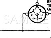
Top leg is power, right is ground, the last goes to the sensor. That's as far as it gets broken down.
I think you may already have that answer through process of elimination.
Did you try a fixed resistor in place of the temp sensor yet? With the fixed resistor in place, monitor the voltage on the single wire. Watch what the voltage does when the gauge goes nuts.
Your answer will probably be in that check.
You would love the factory diagram. This is really damn close to what the diagram with your gauge looks like (darn GIS, this is the first one I found)
Top leg is power, right is ground, the last goes to the sensor. That's as far as it gets broken down.
Thread Starter
LOCO!! And The Papers To Prove It
Joined: Apr 2012
Posts: 76
Likes: 0
Rep Power: 0 Re: Pull ECU Codes?
Must be that darn BS in Electrical Engineering.Not Yet....After the swap Meet today.
OK so the meter has inductors(windings), not resistors. What this means is as the sensor resistance goes down, the current in the circuit goes up, causing the current in the inductors(windings) to go up. Greater magnetic field, causing more deflection of the meter. I think.
Single resistor test will give more info. Thanks ezone -Kevin
If you think a good mechanic is expensive, try hiring a bad one
Joined: Dec 2011
Posts: 32,017
Likes: 256
From: Midwest. Aiming about mid-chest
Rep Power: 519 Re: Pull ECU Codes?
Are you sure the bottom leg isn't ground ezone? How come the bottom leg is split?(If it goes to the sensor)
The same generic pic above is used in the diagram for your car (the gauge part of the pic).
Ignore the wire lines on the generic pic.. Imagine they are not there at all. Pay attention to only the round gauge......I gave you the wire designations relative to the gauge terminal position based on reading the diagram for your car, not what was on the pic. Remember, the pic above is generic.
Heck, buy a shop manual for your car and see it for yourself. I can't hotlink the info I use for you, and didn't find an actual diagram on a GIS right away.
OK so the meter has inductors(windings), not resistors. What this means is as the sensor resistance goes down, the current in the circuit goes up, causing the current in the inductors(windings) to go up. Greater magnetic field, causing more deflection of the meter. I think.
The single resistor test I thought of above would probably only show something if one winding in the gauge was intermittently shorting, but you wouldn't see any voltage change if the other winding was shorting (if the layout in the diagram is true). Maybe I'm way off base here too.
Quote:
Originally Posted by ezone
Um, you may be trying to overanalyze it.
Must be that darn BS in Electrical Engineering.
Originally Posted by ezone
Um, you may be trying to overanalyze it.
Must be that darn BS in Electrical Engineering.
Last edited by ezone; Sep 29, 2012 at 10:03 AM.
Thread Starter
LOCO!! And The Papers To Prove It
Joined: Apr 2012
Posts: 76
Likes: 0
Rep Power: 0 Re: Pull ECU Codes?
The single resistor test I thought of above would probably only show something if one winding in the gauge was intermittently shorting, but you wouldn't see any voltage change if the other winding was shorting (if the layout in the diagram is true). Maybe I'm way off base here too.
I think this means all circuits are good except WTF is happening at the sensor.
Came home, car still hot, measured the sensor, 70 ohms. Plugged in the sensor to the gauge. Gauge goes up to a little under half. This sounds good except maybe the resistance is high for the car being hot. Maybe the ground path that I'm putting the ohm meter probe on(dizzy mounting bolt) is adding some resistance?
Let the car cool down. Pulled rad cap and stuck in a thermometer. Put the ohm meter on the sensor and monitored the coolant temperature in the rad neck. Temp goes up to around 186, coolant begins to flow(T-stat opens) Sensor resistance around 68 ohms. Temp continues to rise to 200 F, sensor resistance falls to 57 ohms, fans kick in, temp comes down, sensor resistance goes up to 68 ohms.
All this seems OK. And now I'm sure coolant is flowing by the sensor. And BTW the gauge I installed is behaving as it should.
As I was doing all this and the fans came on I felt a big gust of air come up from right in front of the battery, Hmmm, could the hot air be causing the neg cable on the battery to change? I checked and it didn't seem to be.
I also noticed that the engine shudders, changes pitch and idles at a different speed. I think I remember local Honda man saying something about the engine is controlled by two different inputs and this is the engine switching from one control to the next.
I also noticed when this happens the battery voltage jumps up to about 14.3 VDC. This seems a bit high, but my meter could be wrong. Maybe when I hosed off the engine I fried the regulator on the alternator and its overcharging?
I dunno. The symptoms are not adding up to point to anything yet.
Coming back from Mexico there's a big long hill. Takes about 5 minutes to get down. I shifted the car into neutral and coasted down. Car idling the whole way. Needle stayed hot all the way down, UNTIL, it rolled to a stop at the bottom of the hill.
Things keep pointing to it being electrical, not overheating. I'm going to check the wires going across the top of the rad. I cut and spliced them. Maybe hot air blowing across is causing one to fail.
Hope I'm not boring anyone with the ride. -Kevin
If you think a good mechanic is expensive, try hiring a bad one
Joined: Dec 2011
Posts: 32,017
Likes: 256
From: Midwest. Aiming about mid-chest
Rep Power: 519 Re: Pull ECU Codes?
Maybe the ground path that I'm putting the ohm meter probe on(dizzy mounting bolt) is adding some resistance?
Replaced the sensor with a 100 ohm resistor. Cluster gauge comes up about one quarter of the way. Drove around, freeway, stop, go, fast, slow. No movement at all of the meter. Nada, zip, zero, solid as a rock.
Coming back from Mexico there's a big long hill. Takes about 5 minutes to get down. I shifted the car into neutral and coasted down. Car idling the whole way. Needle stayed hot all the way down, UNTIL, it rolled to a stop at the bottom of the hill.
I think this means all circuits are good except ...
I also noticed that the engine shudders, changes pitch and idles at a different speed. I think I remember local Honda man saying something about the engine is controlled by two different inputs and this is the engine switching from one control to the next.
I also noticed when this happens the battery voltage jumps up to about 14.3 VDC. This seems a bit high, but my meter could be wrong. Maybe when I hosed off the engine I fried the regulator on the alternator and its overcharging?
I also noticed when this happens the battery voltage jumps up to about 14.3 VDC. This seems a bit high, but my meter could be wrong. Maybe when I hosed off the engine I fried the regulator on the alternator and its overcharging?
So maybe isolate:
Gauge grounds at G401: Drivers footwell, just above the left kick panel.
This ground point is used by several other things too. Make certain it is really a good connection, clean and tight.
Attach fixed resistor to this ground, and other end to wiring as before. Retry same test where it acted up previously.
Ummm the sensor wire passes thru 2 different bulk connectors. one inside the dash above the fusebox, the other is on the pass. strut tower, 8 way conn, white color... Any evidence of water inside it? Diesel fuel? Corrosion? Diesel might have done some damage the rubber seals, it is a petroleum product. Water causes some really strange elect. problems. Peel back any separators so you can see all sides of the wiring...
The symptoms are not adding up to point to anything yet.
Thread Starter
LOCO!! And The Papers To Prove It
Joined: Apr 2012
Posts: 76
Likes: 0
Rep Power: 0 Re: Pull ECU Codes?
The failure is very repeatable, car rolling more than 5mph, or the fans come on cause it to scream high. Its like air through the rad makes it fail.
It goes up and comes down really fast. Like 2-3 seconds. Making me believe there's no way the temp is changing that fast....must be electrical.
Here's the hill.
As soon as it gets light outside(and I wake up) I'm going to go through your post thoroughly for inspiration and poke around at the electronics. Maybe I'll get lucky. Thanks kevin

Thread Starter
LOCO!! And The Papers To Prove It
Joined: Apr 2012
Posts: 76
Likes: 0
Rep Power: 0 Re: Pull ECU Codes?
Looks like corn. Me = 0-7 Kansas, 7-14 Nebraska. Miss the thunderstorms, greeness and fireflies, but not the snow, or humidity.
New test:
Unhooked wire to sensor. Hooked alligator clips with wires and alligator clips on the other ends and brought them to where I could reach them.
I can hook/unhook the clips I brought to have the circuit intact or not to measure the resistance.
I know the sensor resistance measures about 62 ohms when the coolant temp is around 200 degrees in the neck of the rad so I bought a 62 ohm resistor and hooked one end to a big ground bolt.
Turned the car on and let it come up to temp, about, 200 degrees. Fans were kicking on and off.
Alligator clips brought out connected together(Normal circuit operation). Cluster gauge reading hot. Unhooked alligator clips. Sensor resistance reads 60 ohms. Hooked cluster gauge wire to fixed 62 ohm resistance and cluster gauge comes down to about 1/4 of the way up.
WTF?? The same resistance is giving a huge difference in gauge reading.
Measured the voltage across the fixed resistor when its hooked up. VDC = 7.2 VDC, Hooked the sensor up and read VDC = 4.7 VDC. I repeated this measurement over and over.
The only thing I can figure out is that the sensor resistance is changing when it gets voltage applied to it/current flowing through it??
This is a new sensor and the old one was acting the same way.
I can't read the sensor resistance with voltage applied. It will frap the meter.
Both the old sensor and new start out cold resistance at about 500 ohms and fall to around 60 ohms when hot. This is not the range that is specified. Only thing that comes to mind now is that the voltage getting applied to the sensors is too much and causing them to fail.
I dunno. Need to let this marinate in my brain a little. Kevin
If you think a good mechanic is expensive, try hiring a bad one
Joined: Dec 2011
Posts: 32,017
Likes: 256
From: Midwest. Aiming about mid-chest
Rep Power: 519 Re: Pull ECU Codes?
Hooked cluster gauge wire to fixed 62 ohm resistance
I assume one end was to the sending unit wire in the engine compartment, what about the other side?
and hooked one end to a big ground bolt.
You got me confused too.
But.
It ain't the fault of the temp sensor (from what you have written). It's somewhere else.
Thread Starter
LOCO!! And The Papers To Prove It
Joined: Apr 2012
Posts: 76
Likes: 0
Rep Power: 0 Re: Pull ECU Codes?
"A" is the resistor. Sorry you can barely make it out. One end is floating free and the other end connected to the adjustment bolt for the dizzy. I apologize for the long wires. I wanted to be able to go all the way into the cab to the gauge if I needed to.
Here's a schematic. Opps sorry about the "and' sign, should be a "7"
One end of the wire with ends/alligator clips "B" hook up to this wire, the wire going inside the cab to the gauge.(You can barely see the connection by the lower "B"). The other end of the wire with ends/alligator clips "B" hooks up to a wire with alligator clip "C". The other end of alligator clip "C" hooks up to the sensor.
As shown in the picture, its in the normal operation mode, gauge hooked up to the sensor.
I can monitor the voltage at the alligator clips C/B. This gives me the voltage being sent back to the gauge by the sensor when the gauge shows fail. This is 4.7 VDC when the gauge reads fail(hot).
I can unhook C/B and measure the resistance of the sensor when the gauge is fail(hot). This is about 60 ohms.
I can move clip "B" to the top of resisitor "A". The voltage at the junction of the resistor and the clip should be the same as I read above. Its not. Its 7.2 VDC. Also the cluster gauge reads fine not hot. Same resistance(close) as the sensor, should give the same reading.
The fixed resistor is 62 ohms. The sensor is reading 60 ohms. All I'm doing is changing the wire going back to the cluster gauge from the sensor to the fixed resistor. The voltage at the wire/alligator clip I'm moving from one to the other should be pretty darn close. (62 vs 60 Ohms)
This is the reason why the gauge is showing hot. Why would the variable resistor(sensor) give a different voltage drop than the exact same fixed resistance? It shouldn't. Unless the variable resistance(sensor) is changing resistance when voltage is applied.
I hope this helps
Thanks ezone. 2 brains are better than one -Kevin
Last edited by atkinson40; Oct 2, 2012 at 11:26 AM.
If you think a good mechanic is expensive, try hiring a bad one
Joined: Dec 2011
Posts: 32,017
Likes: 256
From: Midwest. Aiming about mid-chest
Rep Power: 519 Re: Pull ECU Codes?
At lunch, brief:
You got 1/4 watt resistors? I bet part of the answer is in this.....
What could the watt rating be on something the size of the temp sensor?
With a cold engine, turn the key on (don't start the engine), gauge hooked on fixed resistor. Wait a while. Does the resistor get hot? Heat increases resistance. Resistor is rated as a static value, but with power applied/working load/heat it becomes dynamic and changing.
Like measuring the resistance of a light bulb filament: Cold is one value, but white hot is another. Calculated amps will be one value with a cold filament, but amps will be quite different in operation. Current (amps) will reflect the dynamic change in resistance when hot.
Did I explain that right? Did it make any sense?
Does it have diddly to do with the problem at hand?
Thread Starter
LOCO!! And The Papers To Prove It
Joined: Apr 2012
Posts: 76
Likes: 0
Rep Power: 0 Re: Pull ECU Codes?
At lunch, brief:
You got 1/4 watt resistors? I bet part of the answer is in this.....
What could the watt rating be on something the size of the temp sensor?
With a cold engine, turn the key on (don't start the engine), gauge hooked on fixed resistor. Wait a while. Does the resistor get hot? Heat increases resistance. Resistor is rated as a static value, but with power applied/working load/heat it becomes dynamic and changing.
Like measuring the resistance of a light bulb filament: Cold is one value, but white hot is another. Calculated amps will be one value with a cold filament, but amps will be quite different in operation. Current (amps) will reflect the dynamic change in resistance when hot.
Did I explain that right? Did it make any sense?
Does it have diddly to do with the problem at hand?
You got 1/4 watt resistors? I bet part of the answer is in this.....
What could the watt rating be on something the size of the temp sensor?
With a cold engine, turn the key on (don't start the engine), gauge hooked on fixed resistor. Wait a while. Does the resistor get hot? Heat increases resistance. Resistor is rated as a static value, but with power applied/working load/heat it becomes dynamic and changing.
Like measuring the resistance of a light bulb filament: Cold is one value, but white hot is another. Calculated amps will be one value with a cold filament, but amps will be quite different in operation. Current (amps) will reflect the dynamic change in resistance when hot.
Did I explain that right? Did it make any sense?
Does it have diddly to do with the problem at hand?
I need to find a way to prove the sensor is changing resistance when voltage is applied and why. The old sensor was acting the same way. Only explanation is if the new sensor failed the same way as the old one did.
The resistance I'm measuring on both is not what you stated it should be. Both read over 500 ohms cold and fall down to 60 ohms hot.
My local autozone doesn't have any more sensors. I'm thinking of taking a trip to the dealer and measuring one or even the junk yard. I haven't had a field trip to the JY in awhile. -Kevin
If you think a good mechanic is expensive, try hiring a bad one
Joined: Dec 2011
Posts: 32,017
Likes: 256
From: Midwest. Aiming about mid-chest
Rep Power: 519 Re: Pull ECU Codes?
Oops
The resistance I'm measuring on both is not what you stated it should be. Both read over 500 ohms cold and fall down to 60 ohms hot.
The sensor will vary resistance throughout all natural temp ranges from -40 to something like close to 300F.
500 ohms will be in that range somewhere. Room temp?
These were right out of the service info:
133F = C mark = 142 ohms
185F = 49 ohm
212F = 32 ohm
My local autozone doesn't have any more sensors. I'm thinking of taking a trip to the dealer and measuring one or even the junk yard. I haven't had a field trip to the JY in awhile. -Kevin
Thread Starter
LOCO!! And The Papers To Prove It
Joined: Apr 2012
Posts: 76
Likes: 0
Rep Power: 0 Re: Pull ECU Codes?
I never gave you a number for cold, other than the C mark on the gauge is supposed to be 133 deg F.
The sensor will vary resistance throughout all natural temp ranges from -40 to something like close to 300F.
500 ohms will be in that range somewhere. Room temp?
These were right out of the service info:
133F = C mark = 142 ohms
185F = 49 ohm
212F = 32 ohm
Then I'll reinstall the sensor and monitor the resistance w/o voltage applied. This will give me the definitive temp where it mounts in the head and calm my fears about the car overheating.
Also I can inspect the sensor and where it mounts in the head. I don't think I was dumb enough to put Teflon tape, but maybe. Also maybe the shop that resurfaced the head over sprayed paint in the hole where the sensor mounts and I can check for this.
I get not needing to know why. I can let that go if I know what. Right now I'm still not positive about what. I think I need a little more about why to figure out what. Thanks for your patience ezone. -Kevin
If you think a good mechanic is expensive, try hiring a bad one
Joined: Dec 2011
Posts: 32,017
Likes: 256
From: Midwest. Aiming about mid-chest
Rep Power: 519 Re: Pull ECU Codes?
make a resistance vs temp chart.
definitive temp where it mounts in the head and calm my fears
Also I can inspect the sensor and where it mounts in the head. I don't think I was dumb enough to put Teflon tape, but maybe. Also maybe the shop that resurfaced the head over sprayed paint in the hole where the sensor mounts and I can check for this.
I get not needing to know why. I can let that go if I know what. Right now I'm still not positive about what. I think I need a little more about why to figure out what. Thanks for your patience

