
DIY: Blue LED gauge and dash lights


Thread Starter
Joined: Sep 2002
Posts: 51,241
Likes: 20
From: NV
Rep Power: 811 

This DIY was done by AlienX and adds to the blue glow needles.
I will make some slight suggestions/improvements to gearbox's DIY for the gauge cluster.
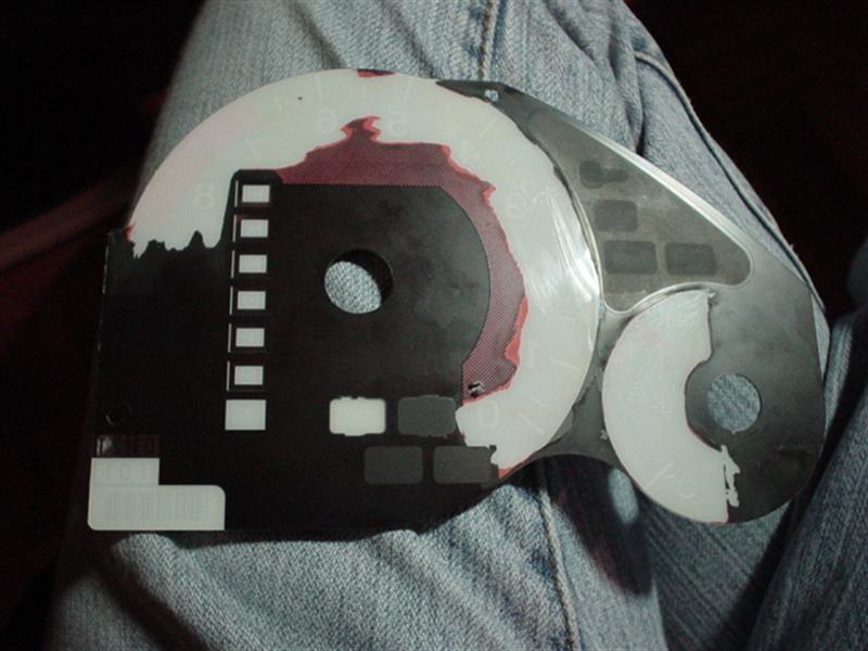
After clearing your gauge faces make sure that you have proper light going though and that you removed all the appropriate orange.
Take your gauge face and put it to a light source, this will reveal if you have missed, or improperly removed the orange filter.

When preparing the needles, I suggest giving the needle a light sand at the bottom and top with a very fine sandpaper. This will help diffuse the light and make your needles brighter. Also paint the bottom with a thin layer of white glass paint, which I did not do.
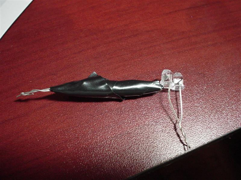
When preparing the LEDs make sure that you have soldered the proper anode and cathode on the LEDs together and use some electrical tape to protect them from short circuiting.
Always remember to add a load limiting resistor to your LEDs. The value of the resistor will vary on your selection of LED. You have to use Ohm's Law to figure out the proper value, or just ask someone where you got the LED from. Remember that you are not connecting the LED to a 12v circuit but a 14v. This makes a difference because when you are running the car your alternator runs at 14v to charge the battery. You don’t want LEDs blowing because then you have to remove everything and install new ones.
Some tips on diffusing the light more evenly.
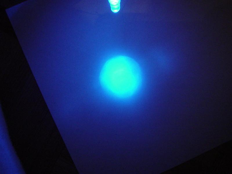
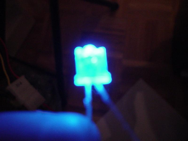
This is a normal LED light pattern.
This is an LED that is either sanded down, or has been broken with needle nose pliers because you didn’t have sandpaper
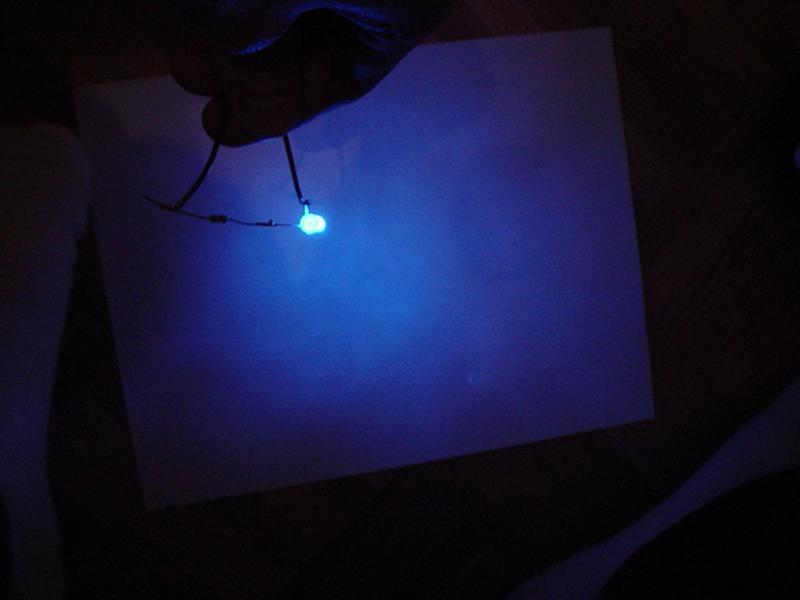
This is what a LED broken with needlenose pilars looks like
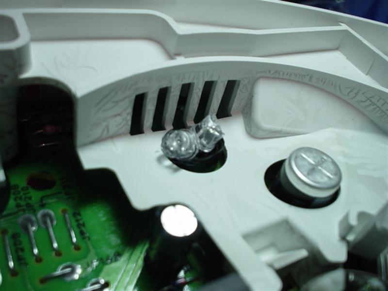
Now, the way I installed my LEDs was 2 per hole, and there are 5 holes. Thats 10 LEDs kids...

You want to aim your LEDs at the white plastic, now the gauge face, you also want to aim them at the light guide so your needles can light up without installing additional LEDs.
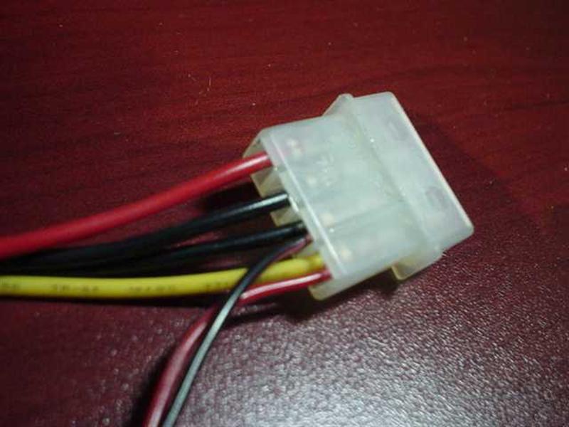
If you have a 12v power supply in your house you can test the LEDs without even connecting them to your car. This will help you aim them correctly. You can use your computer as a 12v power supply. Connecting a wire to the yellow power connector is +12 and the black wire beside it is the ground.
This is what it looks like when the LEDs are aimed up instead of at the white plastic.
you can see that the light is not distributed evenly..
This is with the LEDs aimed at the white plastic.
I am covering the needle light guide with my finger in that picture.
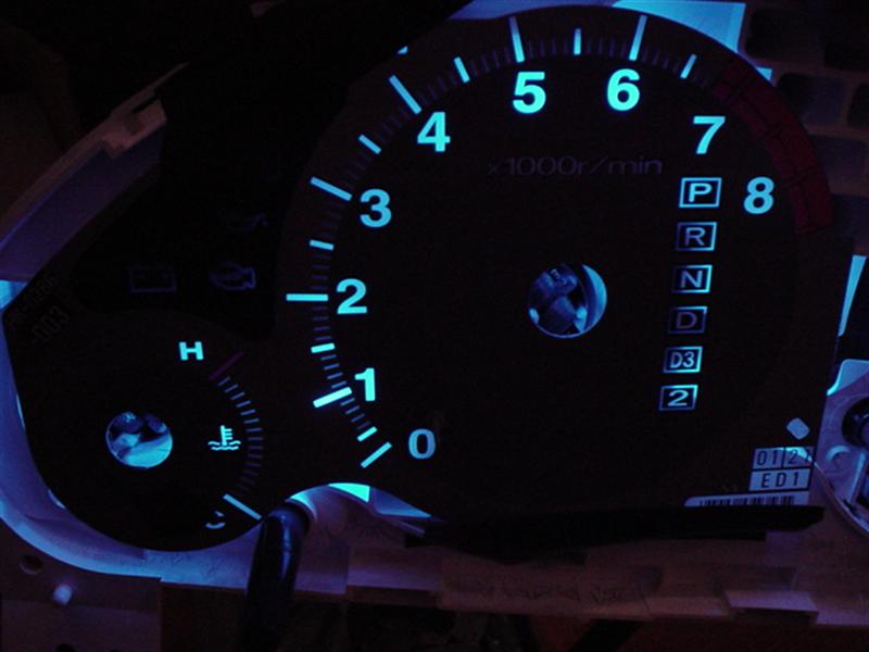
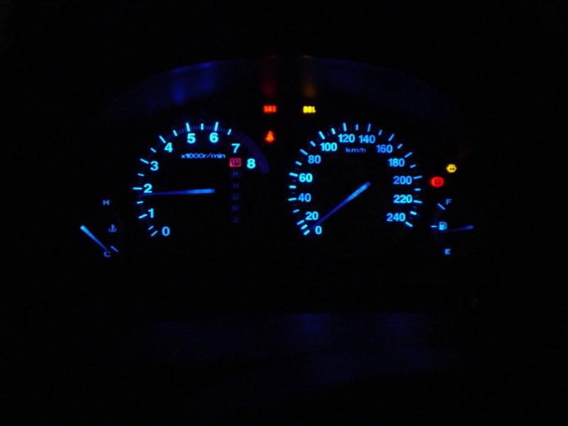
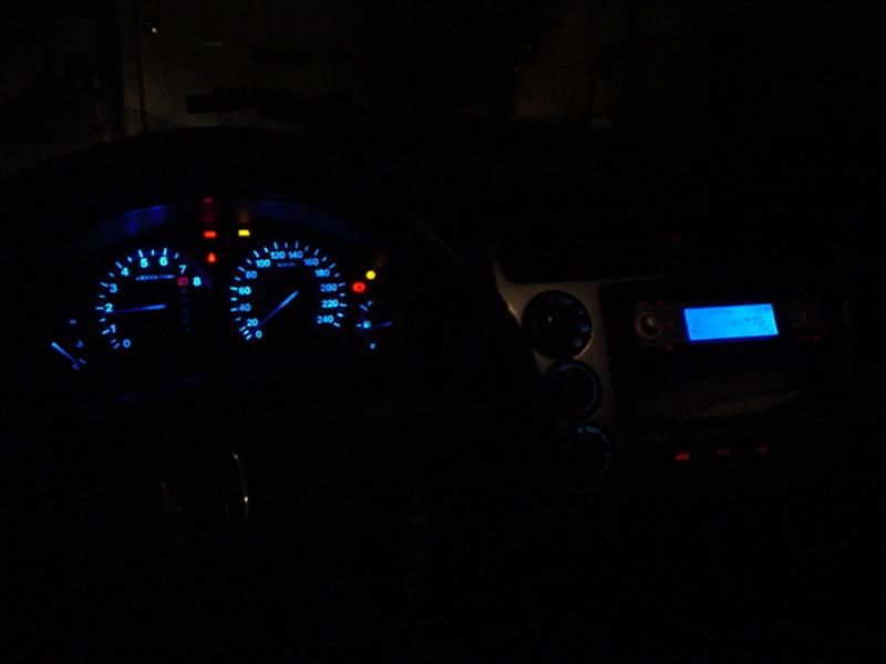
This is the whole cluster.
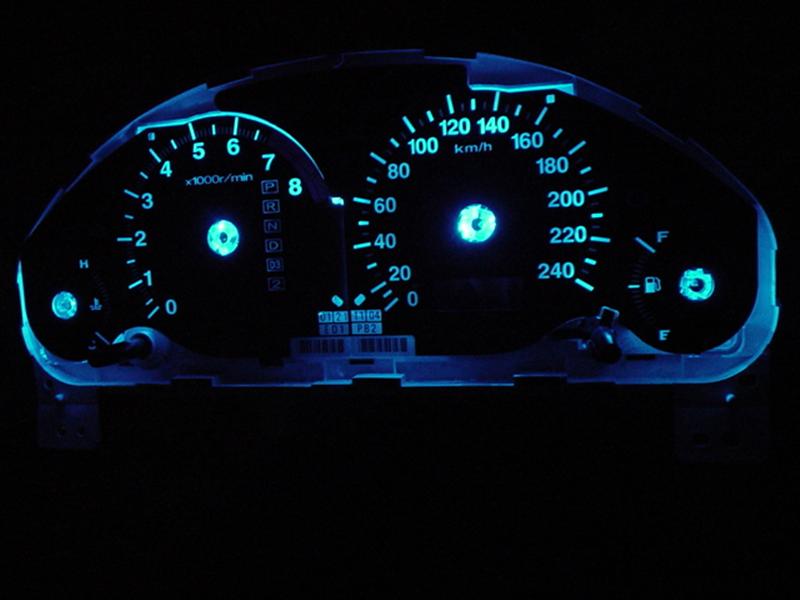
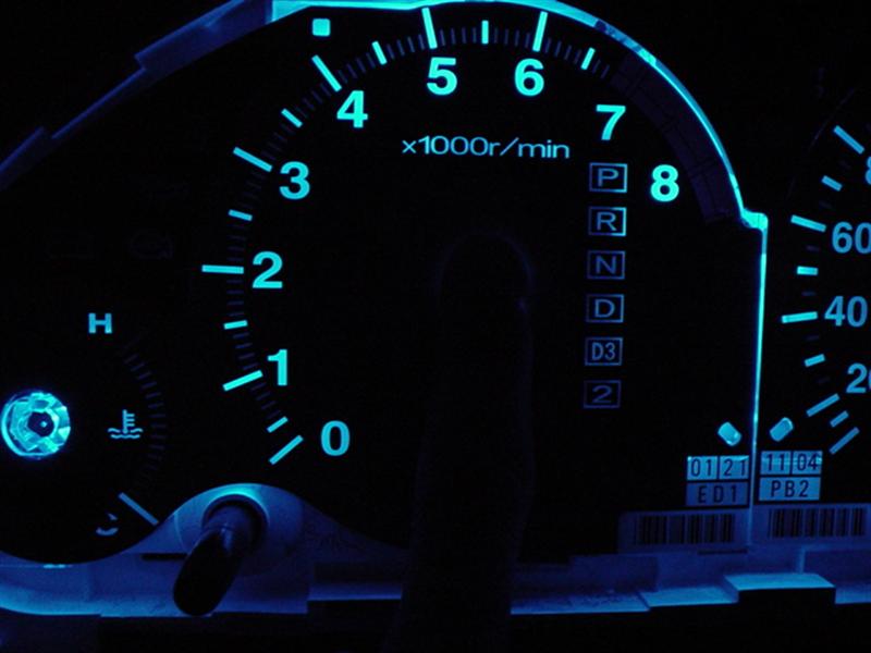
The tach looks uneven in this picture because it’s not fully pressed in. The speedo is uneven and I later added 3 more LEDs to compensate because the light was being blocked by electrical components.
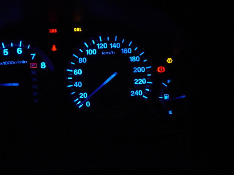
Speedo with Needle, no extra LEDs added under the needle..
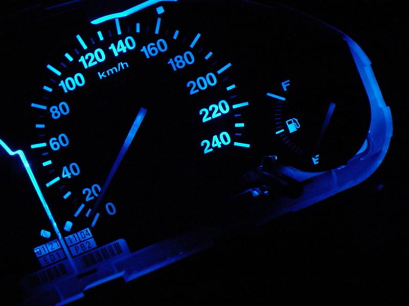
LED light is uneven, and 3 extra LEDs were added to compensate.
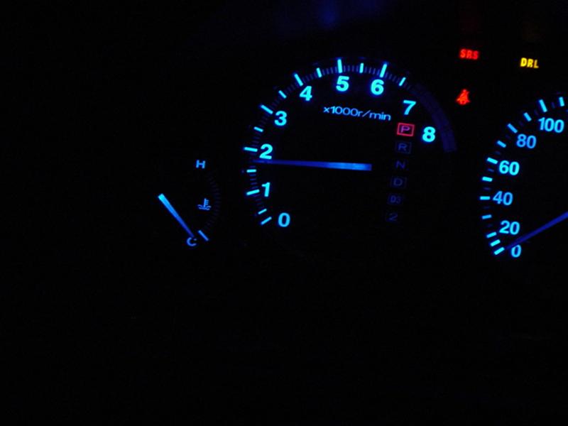
Tach with Needle,

Light is even in this picture.
FINAL RESULTS !!!!!!!!!!
Addition:
If you attempt this LED install, you might screw up your needle calibration.. like I did... YA YA !!
I found a very easy fix which should take anyone's worries away on fixing it.
I will tell you just incase you run into this problem yourself ever in the future.
With the cluster opened and needles not installed connect the cluster to your car, turn your key to the "on" position. This will set the little pins which you stick your needles in to 0. Now just insert the needles ( speedo and tach ) to 0 while fuel to F ( after filling the tank to full ) and temp to C ( after you are sure the engine is cooled down )
now get a buddy to pace you and make sure you are running at the correct speed, and for RMP try to redline and see if your limiter turns on. Temp should be steady in the middle, and gas.. well the civic gas guages is messed up period but if you low on gas your gas light will turn on.
I will make some slight suggestions/improvements to gearbox's DIY for the gauge cluster.
After clearing your gauge faces make sure that you have proper light going though and that you removed all the appropriate orange.
Take your gauge face and put it to a light source, this will reveal if you have missed, or improperly removed the orange filter.
When preparing the needles, I suggest giving the needle a light sand at the bottom and top with a very fine sandpaper. This will help diffuse the light and make your needles brighter. Also paint the bottom with a thin layer of white glass paint, which I did not do.
When preparing the LEDs make sure that you have soldered the proper anode and cathode on the LEDs together and use some electrical tape to protect them from short circuiting.
Always remember to add a load limiting resistor to your LEDs. The value of the resistor will vary on your selection of LED. You have to use Ohm's Law to figure out the proper value, or just ask someone where you got the LED from. Remember that you are not connecting the LED to a 12v circuit but a 14v. This makes a difference because when you are running the car your alternator runs at 14v to charge the battery. You don’t want LEDs blowing because then you have to remove everything and install new ones.
Some tips on diffusing the light more evenly.
This is a normal LED light pattern.
This is an LED that is either sanded down, or has been broken with needle nose pliers because you didn’t have sandpaper
This is what a LED broken with needlenose pilars looks like
Now, the way I installed my LEDs was 2 per hole, and there are 5 holes. Thats 10 LEDs kids...
You want to aim your LEDs at the white plastic, now the gauge face, you also want to aim them at the light guide so your needles can light up without installing additional LEDs.
If you have a 12v power supply in your house you can test the LEDs without even connecting them to your car. This will help you aim them correctly. You can use your computer as a 12v power supply. Connecting a wire to the yellow power connector is +12 and the black wire beside it is the ground.
This is what it looks like when the LEDs are aimed up instead of at the white plastic.
you can see that the light is not distributed evenly..
This is with the LEDs aimed at the white plastic.
I am covering the needle light guide with my finger in that picture.
This is the whole cluster.
The tach looks uneven in this picture because it’s not fully pressed in. The speedo is uneven and I later added 3 more LEDs to compensate because the light was being blocked by electrical components.
Speedo with Needle, no extra LEDs added under the needle..
LED light is uneven, and 3 extra LEDs were added to compensate.
Tach with Needle,
Light is even in this picture.
FINAL RESULTS !!!!!!!!!!
Addition:
If you attempt this LED install, you might screw up your needle calibration.. like I did... YA YA !!
I found a very easy fix which should take anyone's worries away on fixing it.
I will tell you just incase you run into this problem yourself ever in the future.
With the cluster opened and needles not installed connect the cluster to your car, turn your key to the "on" position. This will set the little pins which you stick your needles in to 0. Now just insert the needles ( speedo and tach ) to 0 while fuel to F ( after filling the tank to full ) and temp to C ( after you are sure the engine is cooled down )
now get a buddy to pace you and make sure you are running at the correct speed, and for RMP try to redline and see if your limiter turns on. Temp should be steady in the middle, and gas.. well the civic gas guages is messed up period but if you low on gas your gas light will turn on.
Last edited by civicDave; May 15, 2007 at 09:57 AM.
Registered!!
iTrader: (2)
Joined: Feb 2003
Posts: 1,279
Likes: 0
From: Mississauga, Ontario, Canada
Rep Power: 295 Alright 1 More addition from the master Alien 
Center Console DIY
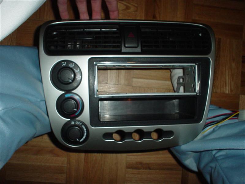
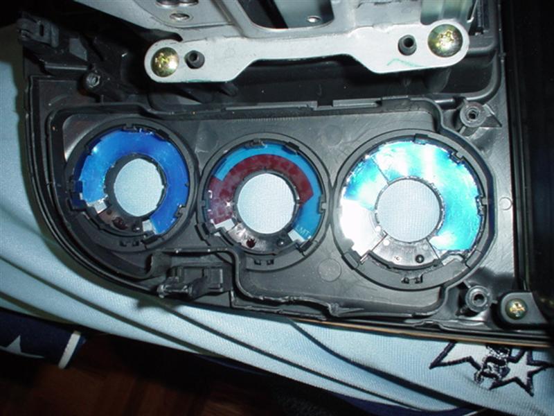
1: Remove Centre Console. Look in DIY section. Quite easy, just remove the utility section, unscrew the two screws underneath, and pull the center console out. Unplug all connections.
Once removed it should look something like this if you have installed an aftermarkey deck.
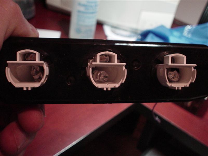
2: Remove the Heat, Fan, and Circulation *****. This is done by just pulling them out.
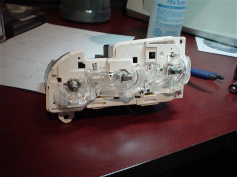
3: Turn the center console over, you will find screws holding the AC Console, and Heat Controls, these will be the big goldish like screws. Remove them. Now the controls should come out. If not, you have done something wrong. Scroll down if you wish to see what these controls look like. Remove the clear light guides. Remove the screw and unclip it. Remove the bulbs with a flat head screw driver, just turn they will come out.
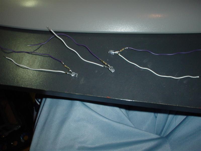
4: Make 3 LEDs for your AC, Defrost, and Recirculate buttons. Make 4 LEDs for the Heat, Fan, and circulation controls. Wire the LEDs up. Sand down the tips to difuse the light.
5: Insert 2 LEDs per bulb hole in the Heat, Fan, and Circulation controls. Aim them outwards.
6: Make the LEDs stay some how, either by adding enough e-tape so that it will get stuck in the hole, then glue it, or just glue them down.
7: Insert 1 bulb per button for the AC/Defrost/Recirculate Buttons. Again, make them stick some how. The LED should be pretty far in the button so that the light will spread evenly.
8: Remove the Orange filter paper on the back of the console for the Heat, Fan and Circulation. Mine was changed from Orange to Blue so mind the colouring.
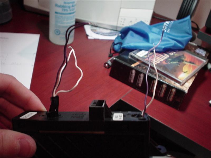
9: Now that you have everything inserted, screwed back into place, and wired. Connect the gounds together, and the power together. From there you will splice into the AC/Defrost/Recirculate plug. I do not have a picture of this. But I can tell you that the two wires that you will splice into are both red, they are on the very right side at the end. The one closest to the end is the ground, while the one of the left of it is the power. That might be vise versa But if it is, dont worry, you can't blow your LEDs.
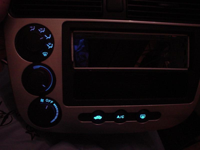
ENJOY !!!!!!! If you have any question, feel free to PM
Almost forgot.. your final result should look something like this.
Center Console DIY
1: Remove Centre Console. Look in DIY section. Quite easy, just remove the utility section, unscrew the two screws underneath, and pull the center console out. Unplug all connections.
Once removed it should look something like this if you have installed an aftermarkey deck.
2: Remove the Heat, Fan, and Circulation *****. This is done by just pulling them out.
3: Turn the center console over, you will find screws holding the AC Console, and Heat Controls, these will be the big goldish like screws. Remove them. Now the controls should come out. If not, you have done something wrong. Scroll down if you wish to see what these controls look like. Remove the clear light guides. Remove the screw and unclip it. Remove the bulbs with a flat head screw driver, just turn they will come out.
4: Make 3 LEDs for your AC, Defrost, and Recirculate buttons. Make 4 LEDs for the Heat, Fan, and circulation controls. Wire the LEDs up. Sand down the tips to difuse the light.
5: Insert 2 LEDs per bulb hole in the Heat, Fan, and Circulation controls. Aim them outwards.
6: Make the LEDs stay some how, either by adding enough e-tape so that it will get stuck in the hole, then glue it, or just glue them down.
7: Insert 1 bulb per button for the AC/Defrost/Recirculate Buttons. Again, make them stick some how. The LED should be pretty far in the button so that the light will spread evenly.
8: Remove the Orange filter paper on the back of the console for the Heat, Fan and Circulation. Mine was changed from Orange to Blue so mind the colouring.
9: Now that you have everything inserted, screwed back into place, and wired. Connect the gounds together, and the power together. From there you will splice into the AC/Defrost/Recirculate plug. I do not have a picture of this. But I can tell you that the two wires that you will splice into are both red, they are on the very right side at the end. The one closest to the end is the ground, while the one of the left of it is the power. That might be vise versa
But if it is, dont worry, you can't blow your LEDs. ENJOY !!!!!!! If you have any question, feel free to PM
Almost forgot.. your final result should look something like this.
Last edited by civicDave; May 15, 2007 at 10:03 AM.


Thread Starter
Joined: Sep 2002
Posts: 51,241
Likes: 20
From: NV
Rep Power: 811 Nope. Won't work for some reason. I've got mine tied into the illumination wire going to the gauge cluster, but they don't adjust. Why would you want them dim anyway? Blue isn't a bright color to begin with.
Thread Starter
Joined: Sep 2002
Posts: 51,241
Likes: 20
From: NV
Rep Power: 811 Yeah, I think you said you wired them from the actual plugs or something. Is your backlight really that blue? Mine came out with a little greenish tint to it.
Thread Starter
Joined: Sep 2002
Posts: 51,241
Likes: 20
From: NV
Rep Power: 811 I noticed in your pic that there's an entire white layer on the back of the numbers. When I cleared mine, only the numbers were white. Maybe that's why it's not getting bright enough. I'm gonna try one more thing. If that doesn't work, I may just get a bunch of blue LEDs and go nuts back there.
Have you seen how bright the accord gauges are? You can see those white numbers from very far away.
Have you seen how bright the accord gauges are? You can see those white numbers from very far away.
Registered!!
iTrader: (7)
Joined: Dec 2001
Posts: 528
Likes: 0
From: North York, Ontario, Canada
Rep Power: 0 saweeeeeet! I've been talking back-and-forth with Gearbox in his thread about this mod. I'm not sure what route I'll take - I think I'll try something along the lines of yours first. Looks pretty clean.
I was just wondering what your needles look like durring the day without the light on and also what color are the original bulbs for the cluseter? Thanks.
Last edited by cosmo; Feb 22, 2004 at 07:21 PM.
Thread Starter
Joined: Sep 2002
Posts: 51,241
Likes: 20
From: NV
Rep Power: 811 Well, my needles are white, and AlienX's are clear because he sanded the backs instead of painting.
Bulbs are regular amber color (clear bulbs). The color is gotten by the filter on the back of the gauges.
Bulbs are regular amber color (clear bulbs). The color is gotten by the filter on the back of the gauges.
Originally posted by gearbox
Well, my needles are white, and AlienX's are clear because he sanded the backs instead of painting.
Bulbs are regular amber color (clear bulbs). The color is gotten by the filter on the back of the gauges.
Well, my needles are white, and AlienX's are clear because he sanded the backs instead of painting.
Bulbs are regular amber color (clear bulbs). The color is gotten by the filter on the back of the gauges.


In case anyone was attempting this diy, the wires you want are at the end just like it says in step 9 except the farthest one (red/black) is the power and the one second from the right (red) is the ground.

Registered!!
iTrader: (2)
Joined: Feb 2003
Posts: 1,279
Likes: 0
From: Mississauga, Ontario, Canada
Rep Power: 295 a resistor does exactly what it says..
but if you can't understand that.. Ill put it to simplier terms..
a resistor is an opposition to current which is contrary to voltage.
wait that might be too complicated also
If you have a 12 volt source ( your car ) a resistor will allow u to run a 3 volt LED by resisting current. Thats better
and about the EL cable thing.. Um.. you would have to talk to gearbox about that one. I was thinking if you add a resistor to the power on the EL cable it will make it darker, I know this works for LEDs but I'm not sure if it would have the same effects on EL cables, and the better question, to what extent can you do that.

