DIY: Grounding kit Install
 04-19-2004
#271
Premium Member
Hey! Look At Me!! I'm a Supporting Member!!
iTrader: (95)

Join Date: Sep 2002
Location: NV
Age: 43
Posts: 51,241
Likes: 0
Received 18 Likes
on
13 Posts
Rep Power: 787 

I attached a ground wire from the alternator casing to the chassis. It didn't do anything. If you mean upgrading the power wires, I don't think that has been done yet.
 04-19-2004
#273
Yes, it's an Acura EL
iTrader: (23)
Join Date: Dec 2002
Location: 416-905, Ontario, Canada
Age: 46
Posts: 8,248
Likes: 0
Received 0 Likes
on
0 Posts
Rep Power: 344 Originally posted by MegaHurtz
Has anybody done their alternator wire upgrade?
If so, please fill me in on ANY information that I might want to know.
Thank you.
Has anybody done their alternator wire upgrade?
If so, please fill me in on ANY information that I might want to know.
Thank you.
Oh btw since you're dealing with live electric connections here, make sure you disconnect the battery terminals first. My buddy forgot to do this when he was helping me out, and when his socket wrench touched the exhaust heat shield, there was a pretty fireworks show, then we had to hunt around Toronto for an open Honda dealership as my batt fuse was blown, LOL. I keep 2 spare batt fuses in the car at all times now, cause I'm paranoid.
04-19-2004
#274
Premium Member
Hey! Look At Me!! I'm a Supporting Member!!
iTrader: (95)
Join Date: Sep 2002
Location: NV
Age: 43
Posts: 51,241
Likes: 0
Received 18 Likes
on
13 Posts
Rep Power: 787 I only have three places grounded to the battery. Alternator is grounded to chassis, and the stock ground to chassis is upgraded. The silver/smoke wires are for the HVS.
http://www.7thgencivic.com/forums/sh...&highlight=hvs

http://www.7thgencivic.com/forums/sh...&highlight=hvs
04-20-2004
#275
Premium Member
Hey! Look At Me!! I'm a Supporting Member!!
iTrader: (95)
Join Date: Sep 2002
Location: NV
Age: 43
Posts: 51,241
Likes: 0
Received 18 Likes
on
13 Posts
Rep Power: 787 Well I just installed a yellow optima today. Huge project, and I had to switch the pos and neg. I'll post pics up tomorrow again.
 04-22-2004
#278
Registered!!

Join Date: Jul 2003
Location: waterford
Age: 40
Posts: 105
Likes: 0
Received 0 Likes
on
0 Posts
Rep Power: 0 hey you know i think it's cool that happies713 made a diy bc i want to go out and do this and i didn't know what to ground it to but to my battery to my tranny. but you know i would of bought happies but i went out and bought 2g wire and some terminals and did a couple my self. i did the body to the block and the body to the #4 valve cover. seriously it did make my head lights brighter and well i don't know to much about the shifting yet but im gonna go out and test it so see ya. happies da man. (thanks for the diy)
05-02-2004
#279
Registered!!
Join Date: Sep 2002
Location: Sacramento, CA
Posts: 175
Likes: 0
Received 0 Likes
on
0 Posts
Rep Power: 0 I got one question...I just found out about that kit from donesixer and I am going to get the basic kit( the block), I already have 20' of wire and was wondering if that was enough to cover the install similar to his kit...I wish I had known about his kit before I bought all that wire...I'dve gotten the whole thing...
05-02-2004
#280
Premium Member
Hey! Look At Me!! I'm a Supporting Member!!
iTrader: (95)
Join Date: Sep 2002
Location: NV
Age: 43
Posts: 51,241
Likes: 0
Received 18 Likes
on
13 Posts
Rep Power: 787 That should be enough to do three or four ground points. Most of them are pretty close to the battery, and you don't have to ground everything. Just doing the three stock grounds will be good.
05-02-2004
#282
Registered!!

Join Date: Apr 2004
Location: Toronto, Canada
Posts: 110
Likes: 0
Received 0 Likes
on
0 Posts
Rep Power: 0 Is there any place where you can get the junction alone without the wires? Im going to DIY the wires but i think it may be slightly better and albeit neater if i do the parralel instead of daisy chaining it but is there any place where you can get the junction? or can we just use any aluminum metal peice that we have drilled holes in?
05-05-2004
#284
THE FIRST LETTER!
Hey! Look At Me!! I'm a Supporting Member!!
Join Date: Aug 2002
Location: CENTRAL, New Jersey, US
Posts: 283
Likes: 0
Received 0 Likes
on
0 Posts
Rep Power: 0 
Originally posted by Mistro
Is there any place where you can get the junction alone without the wires? Im going to DIY the wires but i think it may be slightly better and albeit neater if i do the parralel instead of daisy chaining it but is there any place where you can get the junction? or can we just use any aluminum metal peice that we have drilled holes in?
Is there any place where you can get the junction alone without the wires? Im going to DIY the wires but i think it may be slightly better and albeit neater if i do the parralel instead of daisy chaining it but is there any place where you can get the junction? or can we just use any aluminum metal peice that we have drilled holes in?
http://www.7thgencivic.com/forums/sh...18#post2002418
05-12-2004
#285
Registered!!
Join Date: Sep 2002
Location: Sacramento, CA
Posts: 175
Likes: 0
Received 0 Likes
on
0 Posts
Rep Power: 0 Finailly Did My Grounding Kit...Pics
Well, I finally finished my DIY grounding kit and wanted to share my experience/knowledge with ya'll.
Anyway, I used the "network" system instead of the "daisy chain" setup. Not that I know for sure which one is better, but I thought I could get a cleaner install using this method. I used 2 distribution blocks that I found at www.installationproducts.com under their "distribution blocks" section. They were only $9.90 a piece and did what I needed t to do.

They are designed to be used with 1/0 to 4 ga. I used it as a 4ga to 4ga....Yes, it probably would have been better to use the 1/0 as the input, but considering that I'm going pretty big with the wires anyway, I figured it would be okay.
 4 Gauge Wire ($0.84 a foot. I ordered 40' of clear black, but only used 27')
 4 Gauge Iced Battery Terminal ($3.25 a piece, I got 4 of them in ICE color, only used 3)
 4 Gauge Iced Ring Terminal ($2.25 a piece, I got 3 packs, they come with 4 in a pack, I ended up using 10 total)
Some of the other parts/tools needed:
Lifetime supply of heat shrink tubing...I sued my own heat tubing instead of the rubber that comes with the terminals. The 4 packs come with 2 black covers and 2 red covers. I just wanted to have all of them the same, so I used my own..besides, I go the stuff layin around, why not use it, right? Anyway, you can get this stuff cheap at Parts Express

Handy-Dandy Heat Gun (a hair dryer will do...or if you really want to get ghetto, you can use a lighter...LOL!)

My Mulit Gauge crimper...(not cheap....it's one of the tools I use for my job). To do a ghetto crimp of 4 ga wire, you can use vise grips. Jus ask me how...LOL! (I'm all about improvising when you ain't got the right tool...as a matter of fact, I have about 3 tool ideas that I should submit to Craftsmen or somebody...everyone I show my ideas to, seem to think it should be a real tool...)

And my most precious tool of tools....I love this one...comes in VERY handy with just about everything you can think of....a Dremel with a pencil adpater...

BTW, this is what my crimped ends looked like...

Okay, now the locations I grounded...
1. Throttle Body

2. Factory Chassis Point
3. Tranny

4. Thermostat
5. Thermostat to Radiator Support

6. Firewall

7. Driver Side Shock Tower
8. Alternator

9. Valve Cover

Now, to actually explain a little more...What I did was, use some new terminals on the battery. I first replaced the factory positive terminal with one of my new ICED ones...spiffy, huh?, that was just for looks and to make it similar to the negative terminal. That red wire going to it is connected to my amp. I then replaced the negative terminal and used the 2 4 ga ring terminals to begin my "network". Each on goes to one distribution block on each side of the engine bay.

Passenger Side Distribution Block

Driver Side Distribution Block

As you can see, I didn't use the plastic cover that came with the AudioPipe Distribution blocks. They were too tall to fit in the space I wanted it to go. I specifically picked the location because I wanted my setup somewhat subdued but still easily accessable should I need to replace a wire. That is another reason why I went a toned down color, I don't want it too flashy under my hood, but that is entirely personal preference.
Another point I'd like to bring up is stripping the paint at each point. I made sure to sand down (with my dremel using the wire brush attachment) and finish that the terminal would contact. I've seen it brought up somewhere in some post asking why you should really do this and I just wanted to give my 2 cents on it. If you were to not sand it down, sure the terminal would still be making contact through the bolt head and down into the metal, but when you have it sanded down, you have essentially doubled the "contact patch" of the terminal. Now, instead of just going up through the head of the bolt, it is also going down directly to the chassis. nd isn't his why we are doing this upgrade in the first place....to install a better ground? I made sure that the terminal itself was always in contact with either the block or chassis directly and not sandwiched in between any brackets/bolts.
The wire brush attachment on the dremel...

The firewall grounding point sanded down...

When I installed it onto the valve cover, you MUST sand the point down if you use the same place I did. The valve cover is coated with a finish of some sort and not directly metal. I choose this location because it made for a nice install that was out of the way, easy to run to my distribution block and didn't require too much modification to the spark-plug cover
Without cover (see above image for final install appearance)

Just had to cut about 1/4" off from between these two "arches", not even noticeable n the finished product

Okay, a few pics of the final install. My goal was to make it as invisible as possible. I think I accomplished that...


And now, things that happened when I turned the car on....
The RPMs initially jumped super high. As I sat in the driver seat, I mashed the gas to raise the RPMs. The needle would go lower to 1400 RPMs, stall, then got to 1100 RPMs and idle there. I also smelled a rich gas mixture...actually, it was a very strong smell. I then decided to reset the FI ECU according to the AEM Cold Air Intake DIY
After which, the engine ran rather strong. As for exact improvements. I do FEEL that it runs a little stronger, but that could just be my brain playin tricks. I haven't drivwn at night yet, so I'm not sure how the headlights will respond. I really don't have a meter with me right now anyway to get any accurate readings. But I do have the peace of mind knowing that I have a better electrical system than what it came with...next step...grounding the knock sensor and main ECU....we'll see what that does....
Anyway, I used the "network" system instead of the "daisy chain" setup. Not that I know for sure which one is better, but I thought I could get a cleaner install using this method. I used 2 distribution blocks that I found at www.installationproducts.com under their "distribution blocks" section. They were only $9.90 a piece and did what I needed t to do.
They are designed to be used with 1/0 to 4 ga. I used it as a 4ga to 4ga....Yes, it probably would have been better to use the 1/0 as the input, but considering that I'm going pretty big with the wires anyway, I figured it would be okay.
4 Gauge Wire ($0.84 a foot. I ordered 40' of clear black, but only used 27') 4 Gauge Iced Battery Terminal ($3.25 a piece, I got 4 of them in ICE color, only used 3) 4 Gauge Iced Ring Terminal ($2.25 a piece, I got 3 packs, they come with 4 in a pack, I ended up using 10 total)Some of the other parts/tools needed:
Lifetime supply of heat shrink tubing...I sued my own heat tubing instead of the rubber that comes with the terminals. The 4 packs come with 2 black covers and 2 red covers. I just wanted to have all of them the same, so I used my own..besides, I go the stuff layin around, why not use it, right? Anyway, you can get this stuff cheap at Parts Express
Handy-Dandy Heat Gun (a hair dryer will do...or if you really want to get ghetto, you can use a lighter...LOL!)
My Mulit Gauge crimper...(not cheap....it's one of the tools I use for my job). To do a ghetto crimp of 4 ga wire, you can use vise grips. Jus ask me how...LOL! (I'm all about improvising when you ain't got the right tool...as a matter of fact, I have about 3 tool ideas that I should submit to Craftsmen or somebody...everyone I show my ideas to, seem to think it should be a real tool...)
And my most precious tool of tools....I love this one...comes in VERY handy with just about everything you can think of....a Dremel with a pencil adpater...
BTW, this is what my crimped ends looked like...
Okay, now the locations I grounded...
1. Throttle Body
2. Factory Chassis Point
3. Tranny
4. Thermostat
5. Thermostat to Radiator Support
6. Firewall
7. Driver Side Shock Tower
8. Alternator
9. Valve Cover
Now, to actually explain a little more...What I did was, use some new terminals on the battery. I first replaced the factory positive terminal with one of my new ICED ones...spiffy, huh?, that was just for looks and to make it similar to the negative terminal. That red wire going to it is connected to my amp. I then replaced the negative terminal and used the 2 4 ga ring terminals to begin my "network". Each on goes to one distribution block on each side of the engine bay.
Passenger Side Distribution Block
Driver Side Distribution Block
As you can see, I didn't use the plastic cover that came with the AudioPipe Distribution blocks. They were too tall to fit in the space I wanted it to go. I specifically picked the location because I wanted my setup somewhat subdued but still easily accessable should I need to replace a wire. That is another reason why I went a toned down color, I don't want it too flashy under my hood, but that is entirely personal preference.
Another point I'd like to bring up is stripping the paint at each point. I made sure to sand down (with my dremel using the wire brush attachment) and finish that the terminal would contact. I've seen it brought up somewhere in some post asking why you should really do this and I just wanted to give my 2 cents on it. If you were to not sand it down, sure the terminal would still be making contact through the bolt head and down into the metal, but when you have it sanded down, you have essentially doubled the "contact patch" of the terminal. Now, instead of just going up through the head of the bolt, it is also going down directly to the chassis. nd isn't his why we are doing this upgrade in the first place....to install a better ground? I made sure that the terminal itself was always in contact with either the block or chassis directly and not sandwiched in between any brackets/bolts.
The wire brush attachment on the dremel...
The firewall grounding point sanded down...
When I installed it onto the valve cover, you MUST sand the point down if you use the same place I did. The valve cover is coated with a finish of some sort and not directly metal. I choose this location because it made for a nice install that was out of the way, easy to run to my distribution block and didn't require too much modification to the spark-plug cover
Without cover (see above image for final install appearance)
Just had to cut about 1/4" off from between these two "arches", not even noticeable n the finished product
Okay, a few pics of the final install. My goal was to make it as invisible as possible. I think I accomplished that...
And now, things that happened when I turned the car on....
The RPMs initially jumped super high. As I sat in the driver seat, I mashed the gas to raise the RPMs. The needle would go lower to 1400 RPMs, stall, then got to 1100 RPMs and idle there. I also smelled a rich gas mixture...actually, it was a very strong smell. I then decided to reset the FI ECU according to the AEM Cold Air Intake DIY
After which, the engine ran rather strong. As for exact improvements. I do FEEL that it runs a little stronger, but that could just be my brain playin tricks. I haven't drivwn at night yet, so I'm not sure how the headlights will respond. I really don't have a meter with me right now anyway to get any accurate readings. But I do have the peace of mind knowing that I have a better electrical system than what it came with...next step...grounding the knock sensor and main ECU....we'll see what that does....

 07-29-2012
#290
Premium Member
Hey! Look At Me!! I'm a Supporting Member!!
iTrader: (95)
Join Date: Sep 2002
Location: NV
Age: 43
Posts: 51,241
Likes: 0
Received 18 Likes
on
13 Posts
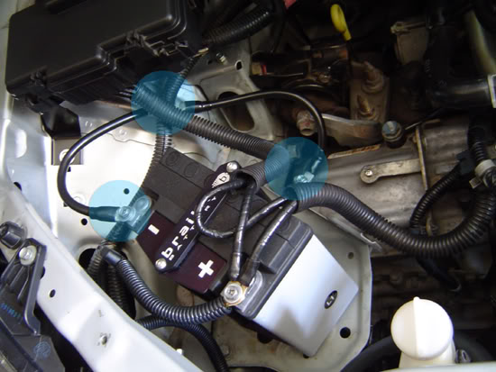
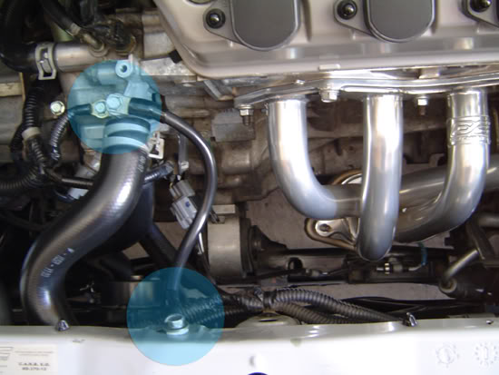
Rep Power: 787 Re: DIY: Grounding kit Install
this is all you need to know. upgrade factory grounds with nice 4 gauge wire and ring terminals. i used premade versions from batteries plus. blue circles denote connection points. you need 3 cables total. negative to chassis, chassis to trans, and engine to chassis.
08-01-2012
#292
 15 lbs battery which is more than enough for me. 425 cca i believe.
  04-11-2013
#294
03 Civic EX

Join Date: May 2012
Location: MN
Posts: 32
Likes: 0
Received 0 Likes
on
0 Posts
Rep Power: 0 
Re: DIY: Grounding kit Install
Ran the Big 3 but had 2 extra ground wires with the kit I received. One was just long enough to go from the transmission ground point to a bolt on the firewall that is also holding a bracket (bracket holds throttle wires), the second wire I ran from firewall to driver side strut tower, I used the bolt holding on the power steering reservoir. This is the first time I've ever re-grounded an engine so I want to make sure there is nothing wrong with my configuration or if there would have been a better route to go with the extra wires? Also would there be anything along the firewall that would get too hot that I should be watching out for when running these wires? I'm pretty sure it's all safe, I'm not engine illiterate, just want to make sure, thanks.

Thread
Thread Starter
Honda Civic Forum
Replies
Last Post
jcb111
SOHC D17Ax non-VTEC - VTEC Engine Swaps
9
03-28-2022 07:35 AM
Switch BL4D3
I.C.E. (Audio) & Electrical Upgrades
23
04-24-2015 06:57 PM

